Horse mounting aid assembly
a technology for mounting aids and horses, applied in the field of horsemanship and equestrian equipment, can solve the problems of insurmountable difficulty of mounting on a horse equipped with conventional riding equipment, and additional difficulty for the person
- Summary
- Abstract
- Description
- Claims
- Application Information
AI Technical Summary
Benefits of technology
Problems solved by technology
Method used
Image
Examples
first embodiment
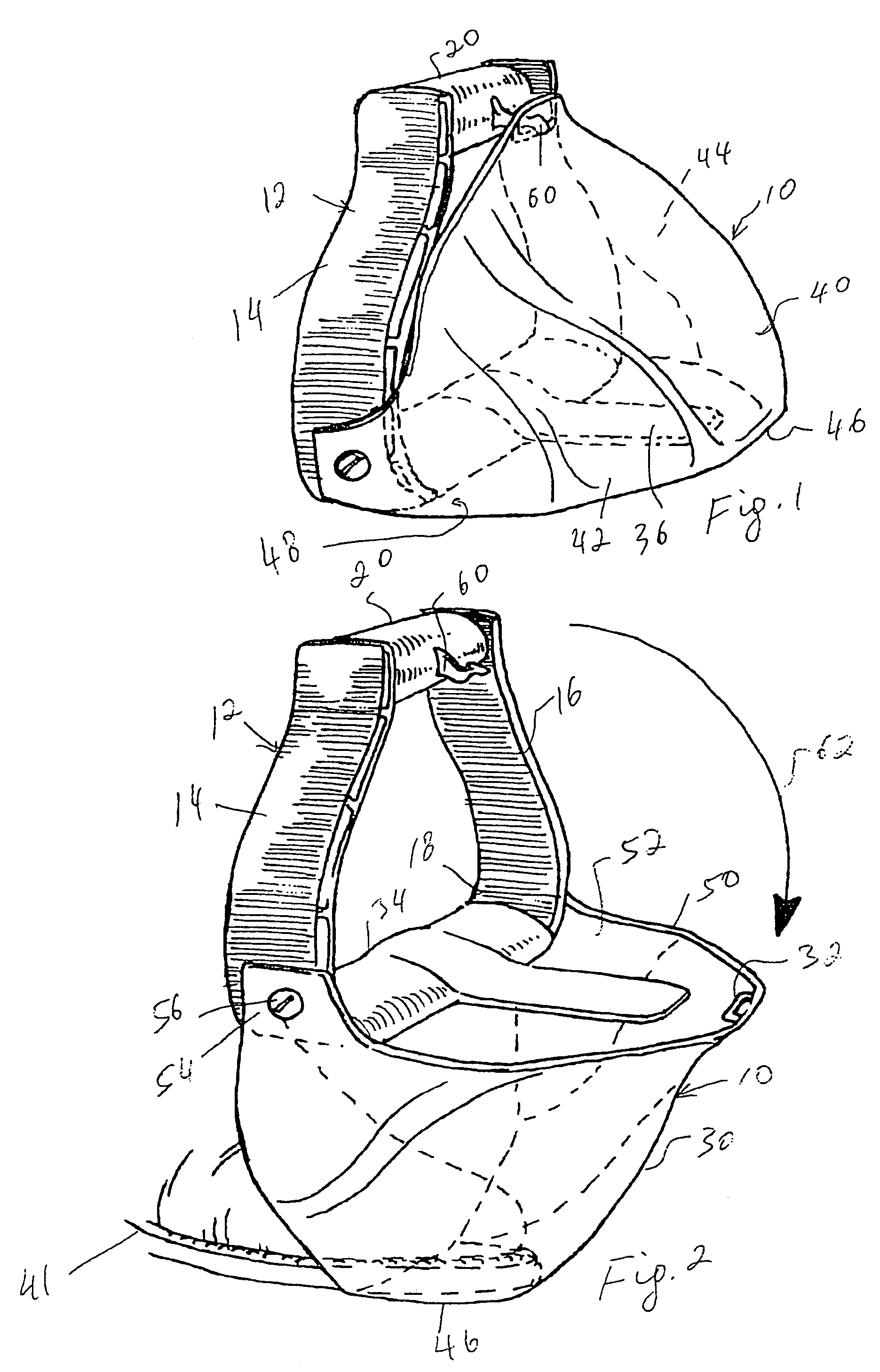
[0014]Turning now to the drawings in more detail, numeral 10 designates the stirrup aid assembly, or mounting aid assembly device in accordance with the present invention, particularly adapted for use with a Western-style stirrup, or stirrup iron 12. As can be seen in the drawing, the stirrup 12 is conventional in a sense that it has a pair of opposed side portions 14 and 16 connected on the bottom by a bottom portion 18. The stirrup 12 has an upper bridge portion 20, to which stirrup leather (not shown) is normally attached.
[0015]The device 10 comprises a body 30 which defines a cavity for receiving at least a portion of a rider's foot therein. The body 30 carries a latching member 32 adapted for engagement with a latch 60 positioned on the upper bridge portion 20. A sleeve 34 is configured for positioning on the bottom portion 18 of the stirrup iron 12 and a safety member 36 is secured to the sleeve 34 extending outwardly therefrom. The body 30 has solid walls defining a central p...
second embodiment
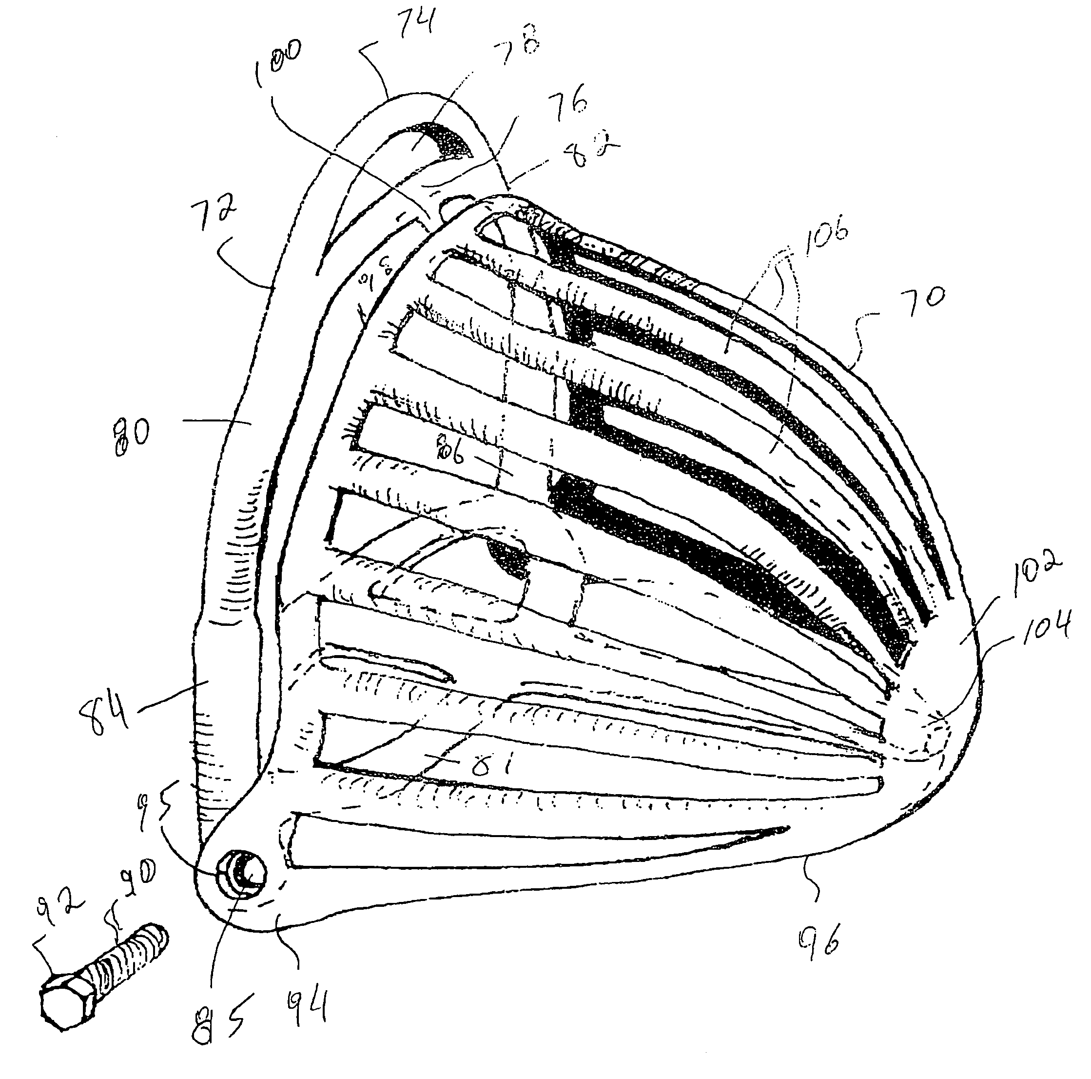
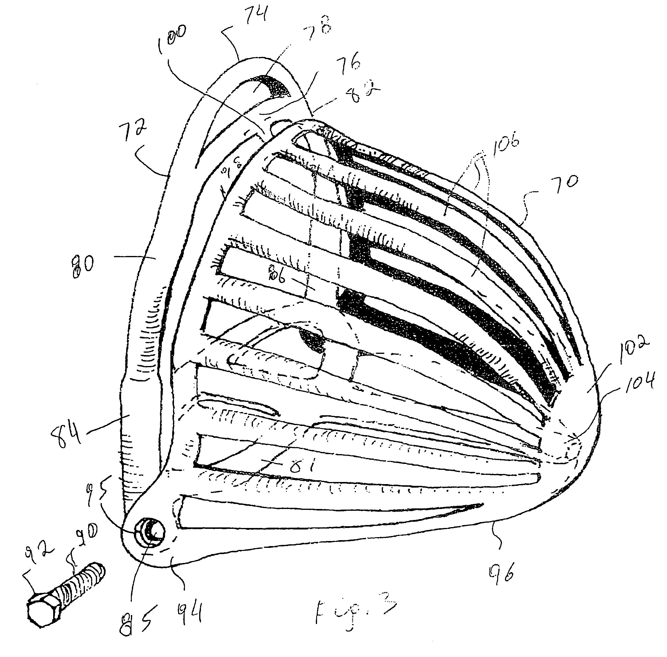
[0023]Turning now to the present invention shown in FIG. 3, a mounting aid device 70 is shown in detail partially secured on an English-style stirrup, or stirrup iron 72. The stirrup 72 has an upper ridge 74 and an intermediate bridge 76. An opening 78 is formed between the bridges 74 and 76 to allow engagement with the stirrup leather (not shown). The stirrup iron 72 has a pair of opposed side portions 80 and 82; each side portion has a lower part, 84 and 86, respectively. The lower parts 84, 86 are provided with openings 85. The diameter of the openings 85 is sufficient to receive a pivot member 90 therethrough. Securing members 92 (only one shown in FIG. 3) prevent disengagement of the pivot member 90 from its engagement with the device 70 and the stirrup 72.
[0024]The device 70 has a pair of opposed attachment portions 94 (only one can be seen in FIG. 3), which are spaced to engage the lower parts 84 and 86 of the side portions 80, 82. Each attachment portion 94 is provided with ...
PUM
 Abstract
Description
Claims
Application Information
 - R&D
- Intellectual Property
- Life Sciences
- Materials
- Tech Scout
- Unparalleled Data Quality
- Higher Quality Content
- 60% Fewer Hallucinations
Browse by: Latest US Patents, China's latest patents, Technical Efficacy Thesaurus, Application Domain, Technology Topic, Popular Technical Reports.
© 2025 PatSnap. All rights reserved.Legal|Privacy policy|Modern Slavery Act Transparency Statement|Sitemap|About US| Contact US: help@patsnap.com


