Pipe disconnector with increased sealing power

a technology of sealing power and disconnector, which is applied in the direction of lighting and heating apparatus, heating types, instruments, etc., can solve the problem of larger sealing power and achieve the effect of improving the tightening power

Active Publication Date: 2009-08-18
HANS SASSERATH GMBH & CO KG
View PDF6 Cites 2 Cited by
  • Summary
  • Abstract
  • Description
  • Claims
  • Application Information

AI Technical Summary

Benefits of technology

[0010]It is an object of the invention to provide a system disconnector of the above mentioned kind with an improved tightening power.
[0012]In such a way a smaller valve seat can be realized for the release valve with a correspondingly higher tightening power without the release valve not functioning anymore at high inlet pressures. A valve seat with smaller seat diameter can be used which operates well at high and at low inlet pressures.
[0013]With increasing inlet pressure at first the release valve is closed. Afterwards the backflow preventer is opened. Then an increased pressure is present in the middle pressure space compared to the previously occurring atmospheric pressure. An increased pressure builds up in the hollow space, too, through the connection between the hollow space and the middle pressure space. This pressure is effective on the shiftable seat. The shiftable seat is moved in the direction of the valve seat up to the casing fixed stop. On the other side the pressure in the hollow space between the shiftable seat, the casing and the release valve body is also effective from the “back side” on the portion extending beyond the release valve body. The area effective for the middle pressure is, therefore, not reduced in such a way even if there is a smaller valve seat. Thereby the relation of the forces at the release valve body remains the same for the reduced valve seat diameter. However, the sealing power is larger, because the sealing has a smaller area. The effective pressurizing power and the quality of the sealing are increased accordingly.

Problems solved by technology

However, the sealing power is larger, because the sealing has a smaller area.

Method used


Image

  • Pipe disconnector with increased sealing power
  • Pipe disconnector with increased sealing power
  • Pipe disconnector with increased sealing power

Examples


Embodiment Construction

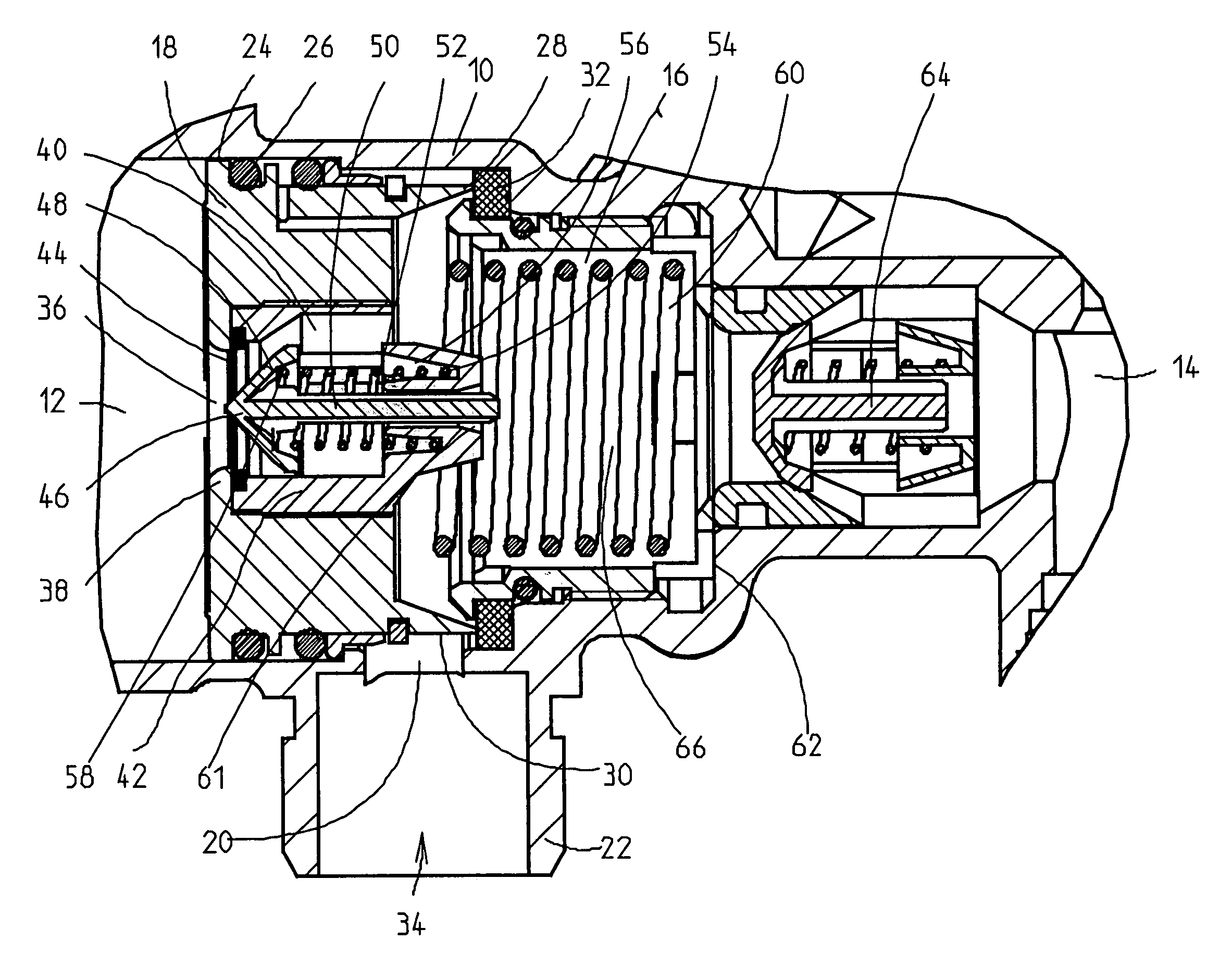
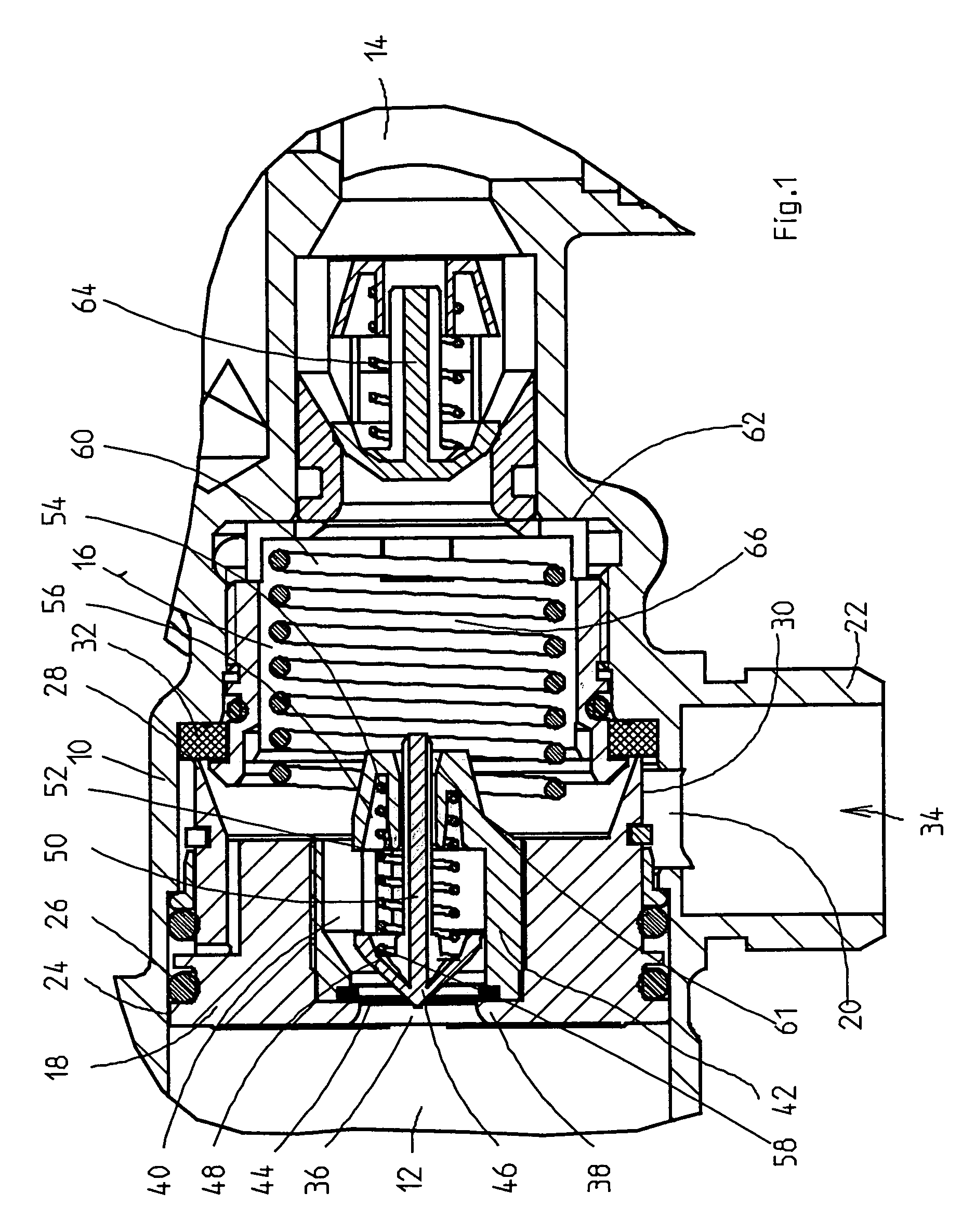
[0024]In FIG. 1 numeral 10 denotes a pipe-like fitting casing. The fitting casing 10 is provided with an inlet 12 and with an outlet 14 at its opposite end. A cylindrical chamber 16 is formed in the casing fitting 10. A piston-shaped valve body 18 is guided in the chamber 16. An outlet 20 branches off the chamber 16, which is provided with an outlet socket 22 connected to the atmosphere.

[0025]The valve body 18 is sealingly guided in the cylindrical chamber 16 with a sealing 26 on its outer surface 24. On its downstream end face 28 the valve body 18 defines an annular valve seat 30. The valve seat 30 abuts a seat sealing 32 in the downstream end position as shown in FIG. 1. The valve body 18 covers the outlet 20 with its outer surface 30. This is a release valve 34.

[0026]The valve body 18 is provided with a central passage 36. An annular flat rim 38 extending towards the inside is formed at the upstream end of the valve body 18. An upstream backflow preventer 40 is arranged in the pa...


PUM


Abstract

A system disconnector for disconnecting an upstream liquid system providing an inlet pressure from a downstream liquid system by a release valve (34) in response to a pressure drop between the systems, includes an upstream backflow preventer (40), a downstream backflow preventer (64) and a release valve body piston (18) arranged between the backflow preventers (40, 64). A pressure difference between the inlet pressure and a middle pressure between the backflow preventers (40,64) counteracts a spring (60) biasing the release valve body in the opening direction, the release valve body (18) having an effective pressurized surface (d) smaller than the surface effective for the inlet pressure. A hollow space (74) defined by the release valve body is connected to the middle pressure (66). A shiftable seat (76) provided in hollow space (74), is movable with respect to the release valve body to a fixed stop (84) upstream of the valve seat (32).

Description

TECHNICAL FIELD[0001]The invention relates to a system disconnector for physically disconnecting an upstream liquid system from a downstream liquid system by means of a release valve in response to a pressure drop between the upstream and downstream liquid system, with an upstream backflow preventer, a downstream backflow preventer and a release valve body in the form of a piston which is, regarding the flow, arranged between the backflow preventers, an inlet pressure of the upstream liquid system upstream from the upstream backflow preventer, a middle pressure in a middle pressure space between the release valve body and the downstream backflow preventer and an outlet pressure of the downstream liquid system downstream of the downstream backflow preventer, wherein a pressure difference between the inlet pressure and the middle pressure counteracts a spring biasing the release valve body in the opening direction and wherein the release valve body has an effective pressurized surface...

Claims


Application Information

Patent Timeline
Patent Type & Authority Patents(United States)
IPC IPC(8): E03C1/10
CPCF24D3/1083F24D3/10Y10T137/2617Y10T137/3331Y10T137/7841
Inventor HECKING, WILLI
Owner HANS SASSERATH GMBH & CO KG
Why Eureka
Try Eureka