
A reinforced coil spring

A tube reel, reinforced technology, applied in the direction of coil springs, springs/shock absorbers, mechanical equipment, etc., can solve the problems of coil springs not tightening, coil spring mechanical fatigue, time-consuming and labor-intensive pulling of tubes and wires, etc. Achieve the effects of enhanced tightening force, low production cost and good overall strength

Active Publication Date: 2022-08-02
YONGKANG HAILI IND
View PDF1 Cites 0 Cited by
  • Summary
  • Abstract
  • Description
  • Claims
  • Application Information

AI Technical Summary

Problems solved by technology

As described; its disadvantages are: when the coil spring is retracted, the coil spring is located at the outermost circle, and the coil spring has a small coil force, and the coil spring will not be tightened when it reaches the coil end, which will affect the hose reel. The effect of using
[0004] The existing solution to the above-mentioned problems is to use a coil spring of appropriate thickness to make a coil spring, so that the outermost coil coil of the coil spring has a suitable tightening force (when the material of the coil spring is the same, the coil spring The winding force is related to the thickness of the coiled reed, and the coiling force of the coiled spring will increase with the increase of the thickness of the coiled reed). A new problem is that when the hose reel pulls out the pipe and wire, the further to the back, the greater the recovery force of the coil spring, the greater the pull-out force required at this time, which makes the pulling out of the pipe and wire time-consuming and laborious. , and long-term tension resistance, it is easy to cause mechanical fatigue of the pipe, wire itself and the coil spring itself, resulting in a decrease in the service life of the pipe, wire and hose reel
In addition, due to tension resistance, the spring clip (ie ear hook) in the existing coil spring will deform as the mechanical fatigue deepens, thus affecting the use effect of the coil spring

Method used


Image

  • A reinforced coil spring
  • A reinforced coil spring
  • A reinforced coil spring

Examples


Embodiment 1

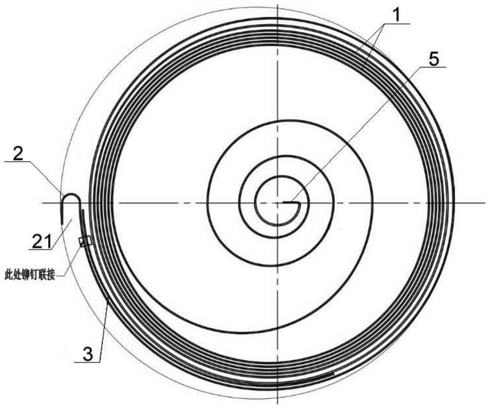
[0020] Example 1: refer to the attached Figure 1-Figure 2 . A reinforced coil spring, comprising a coil spring 1 formed by a coil spring sheet, the outer end of the coil spring 1 is bent to form an ear hook 2, and the opening 21 of the ear hook 2 is located in the outermost ring On the outside of the coil spring, the inner side of the outermost coil spring is provided with a piece of spring steel sheet 3 and the outer end of the spring steel sheet 3 is fixedly connected with the outermost coil spring. The inner end is located between the outermost coil spring and the secondary outer coil; that is, only the outer end of the spring steel sheet 3 is fixedly connected to the outermost coil spring; The length is a quarter of the length of the outermost coil spring. The setting of the length, width and thickness of the spring steel plate 3 plays a role in thickening the outermost coil spring, so that the coil spring can be retracted during the retraction process. The outermost co...

Embodiment 2

[0023] Example 2: On the basis of Example 1, refer to the attached Figure 3-Figure 5 . The spring steel sheet 3 and the coil spring are fixedly connected by one or more rivets 4. The spring steel sheet 3 is provided with a plurality of first rivet holes, and the back of the spring steel sheet 3 is provided with positioning protrusions. The outermost coil spring is provided with a plurality of second rivet holes, and the outermost coil spring is provided with positioning holes 11 and the positioning holes 11 is located between a plurality of second rivet holes, the positioning through hole 11 is a square hole, and the positioning protrusion 32 is square; the size of the square hole matches the size of the square positioning protrusion 32, and the positioning protrusion The first rivet hole on the spring steel sheet 3 and the corresponding second rivet hole on the outermost coil spring sheet are connected one-to-one with the positioning hole 11 concave and convex, so that the ...

Embodiment 3

[0025] Example 3: On the basis of Example 1 and Example 2, refer to the attached Image 6 . The outer end of the spring steel sheet 3 is bent to form an ear hook reinforcement portion 33, and the inner surface of the ear hook reinforcement portion 33 is in close contact with the outer surface of the ear hook 2, and the end of the ear hook reinforcement portion 33 is inwardly rolled. The end and the inner coil end buckle the hook head of the ear hook 2. After the coil spring 1 is formed by the coil spring, the spring steel sheet 3 is riveted with the outermost coil spring, and the outer end surface of the spring steel sheet 3 exceeds The outer end surface of the coil spring is then bent together with the outer end of the spring steel sheet 3 and the outer end of the coil spring by the bending device to form the ear hook 2 and the ear hook reinforcing part 33, and then the ear hook is strengthened. The end of the part 33 is crimped to fasten the hook head of the ear hook 2 .


PUM


Abstract

The invention relates to a kind of reinforcement which can not only enhance the tightening force of the outermost coil spring sheet of the coil spring, but also does not increase the maximum pull-out force of the coil spring, and at the same time can improve the use effect of the ear hook, and at the same time, the production cost is low and the production is convenient. A type reel coil spring, the inner side of the outermost coil spring is provided with a piece of spring steel, and the outer end of the spring steel is fixedly connected with the outermost coil spring, and the inner end of the spring steel is The head is located between the outermost coil spring and the second outer coil spring. Advantages: First, a spring steel sheet added to the reinforced coil spring can not only enhance the tightening force of the outermost coil spring of the coil spring, but also will not increase the maximum pull-out force of the coil spring, and the production cost is low. 2. The ear hook in the coil spring of a reinforced hose reel has better overall strength, and the opening of the ear hook is not easy to expand during use.

Description

technical field [0001] The invention relates to a kind of reinforcement which can not only enhance the tightening force of the outermost coil spring sheet of the coil spring, but also does not increase the maximum pull-out force of the coil spring, and at the same time, can improve the use effect of the ear hook, and at the same time, the production cost is low and the production is convenient. The utility model relates to a coil spring of a type reel, belonging to the technical field of coil springs. Background technique [0002] The hose reel, also known as the winder, the reel, the reel, the drum, and the hose reel, are widely used and are used in various production and assembly workshops, maintenance workshops, car beauty shops, automobile 4S shops and other workplaces. , the applicant is an enterprise specializing in the production of hose reels, and has more than ten years of experience in the research and development of hose reels. The applicant's name includes the in...

Claims


Application Information

Patent Timeline
Patent Type & Authority Patents(China)
IPC IPC(8): F16F1/12F16F1/04
CPCF16F1/12F16F1/04B65H2701/33B65H75/486F16F1/10B65H75/48F16F2238/022
Inventor 邵羽骏
Owner YONGKANG HAILI IND
Learn More