
Transmission connection structure of fan impeller of sweeper truck

A fan impeller and connection structure technology, which is applied in the field of sanitation machinery, can solve the problems of flat key wear, large vibration, and large noise, and achieve the effects of reducing torque and force, prolonging service life, and reducing easy breakage

Pending Publication Date: 2021-10-19
NANJING AEROSUN MORITA ENVIRONMENTAL PROTECTION S&T
View PDF9 Cites 0 Cited by
  • Summary
  • Abstract
  • Description
  • Claims
  • Application Information

AI Technical Summary

Problems solved by technology

[0003] First of all, the working environment of the fan of the road sweeper is relatively complicated, and the vehicle vibrates greatly when driving on the road. When the traditional flat key is used to drive the impeller to rotate, the flat key is prone to wear or break
[0004] Secondly, after the fan works for a long time, the tightness of the connection between the motor shaft and the fan impeller is reduced, and the impeller is prone to loosening, which increases the noise of the fan when it is working, and reduces the performance and life of the cleaning equipment.

Method used


Image

  • Transmission connection structure of fan impeller of sweeper truck
  • Transmission connection structure of fan impeller of sweeper truck
  • Transmission connection structure of fan impeller of sweeper truck

Examples


Embodiment

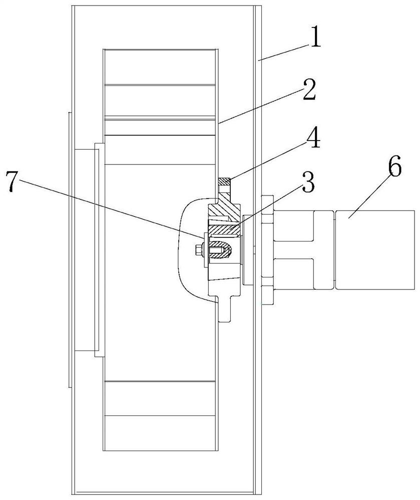
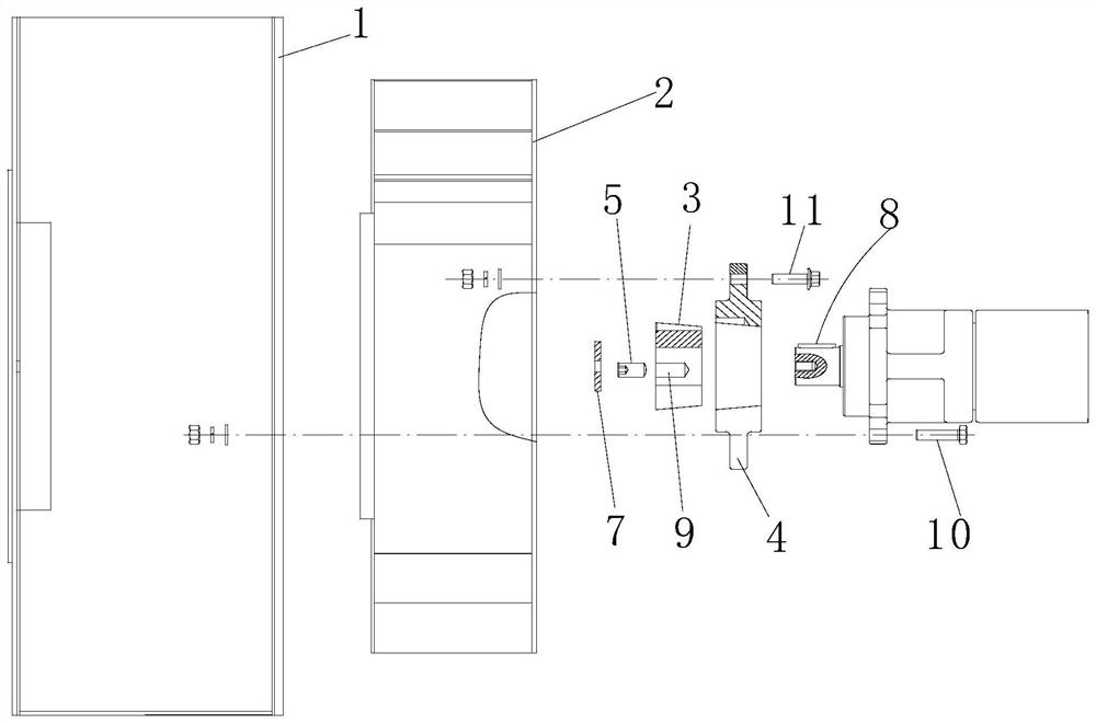
[0022] The transmission connection structure of the fan impeller of the road sweeper of the present embodiment is installed with the fan and the motor as follows: figure 1 and figure 2 As shown, it includes volute 1, impeller 2 inside the volute, tapered bushing 3, impeller flange 4, screw (set screw) 5, motor output shaft 6 and pressure plate 7; volute 1 and motor 6 Fix it with the first fastener 10, fix the impeller flange 4 and the impeller 2 with the second fastener 11, and connect the output shaft (shaft extension) of the motor 6 with the tapered bushing 3 through the flat key 8.

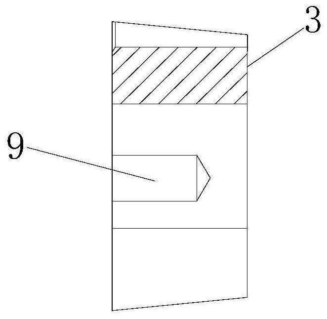
[0023] Such as image 3 As shown, the outer circumference of the tapered bushing 3 forms an outer tapered surface; as Figure 5 As shown, the hollow circumference of the impeller flange 4 forms an inner tapered surface matched with the outer tapered surface of the tapered bushing 3; as figure 1 and figure 2 As shown, the tapered bushing 3 extends into the hollow of the impeller flange fro...


PUM


Abstract

The invention relates to a transmission connection structure of a fan impeller of a sweeper truck, and belongs to the technical field of environmental sanitation machinery. The transmission connection structure comprises a volute, the impeller, a conical shaft sleeve, an impeller flange, set screws, a motor output shaft and a pressing plate. The volute and a motor and the impeller flange and the impeller are fixed by fasteners, and the motor output shaft is connected with the conical shaft sleeve through a flat key; the outer circumference of the conical shaft sleeve is in conical surface fit with the hollow circumference of the impeller flange, the conical shaft sleeve extends into a middle hole of the impeller flange from one side of the conical shaft sleeve, and the pressing plate is attached to the other side of the conical shaft sleeve; the conical shaft sleeve is symmetrically provided with two first semicircular blind holes, a first half-thread through hole and a through slot; the impeller flange is symmetrically provided with two second half-thread through holes and a second semicircular blind hole; and the two first semicircular blind holes and the two second half-thread through holes are oppositely combined to form two first circular holes respectively, the first half-thread through hole and the second semicircular blind hole are oppositely combined to form a second circular hole, and the screws can be screwed into the first circular holes or the second circular hole. According to the transmission connection structure, besides the flat key transmission force, the screwing force, the elastic force and the friction force are increased, so that the connection between the fan impeller and the motor is tighter.

Description

technical field [0001] The invention relates to a transmission connection structure of a fan impeller of a road sweeper, and belongs to the technical field of sanitation machinery. Background technique [0002] With the rapid development of urban construction, the demand for mechanized road cleaning and cleaning equipment has also increased, among which road sweepers and sweepers are the main ones. The core component of the road sweeper and sweeper is the centrifugal fan. As far known, the fan of the road sweeper and the output shaft of the motor are basically connected by a traditional flat key to drive the impeller to rotate. This connection structure has the following defects: [0003] First of all, the working environment of the fan of the road sweeper is relatively complicated, and the vehicle vibrates greatly when driving on the road. When the traditional flat key is used to drive the impeller to rotate, the flat key is prone to wear or breakage. [0004] Secondly, ...

Claims


Application Information

Patent Timeline
Patent Type & Authority Applications(China)
IPC IPC(8): F04D25/08F04D29/28F04D29/62E01H1/08
CPCF04D25/08F04D29/281F04D29/626E01H1/08
Inventor 封慧张晓雷张虹
Owner NANJING AEROSUN MORITA ENVIRONMENTAL PROTECTION S&T
Learn More