Roller for a fibre-processing machine, for example a spinning preparation machine

a technology of processing machine and roller, which is applied in the direction of carding machine, vessel construction details, textiles and paper, etc., can solve the problems of high cost of cylinder end manufacture, high cost of cylinder wall manufacture, and major damage to the high-performance carding machine concerned, so as to improve braking value, reduce the effect of cylinder end manufacturing cost and small thickness

Inactive Publication Date: 2009-08-25
TRUETZSCHLER GMBH & CO KG
View PDF16 Cites 2 Cited by
  • Summary
  • Abstract
  • Description
  • Claims
  • Application Information

AI Technical Summary

Benefits of technology

[0011]The roller according to the invention consists of at least one metal cylinder and an outer ring of hardened fibre-reinforced plastics material. The metal cylinder gives the roller the requisite rigidity and strength. This applies both to the roller wall and to the cylinder ends. As a result of the fact that the wall is surrounded by a sheath of fibre-reinforced plastics material, the thickness (amount) of the sheath can be kept small, which makes possible economical manufacture. Such a sheath limits or avoids (compensates) widening of the cylinder in use due to heat and / or centrifugal force so that, in advantageous and simple manner, the carding nip between the roller clothing and the clothing of a machine element located opposite, for example a revolving or stationary card top, remains substantially or entirely constant. Further advantages in use are, for example, substantially improved braking values, savings in terms of drive units, energy savings, higher production rates, wider working widths and vibration-free running.

Problems solved by technology

In extreme cases, the nip set between the work surfaces can be completely used up as a result of thermal expansion so that components in relative motion collide, causing major damage to the high-performance carding machine concerned.
A disadvantage is the high cost both for manufacture and also for the fibre-reinforced plastics material for the thick cylinder wall.
The cost for manufacture of the cylinder ends is also considerable.
In addition, it is disadvantageous that, in the case of high-speed rollers for fibre-processing machines provided with clothings, the loading circumstances and operating conditions are difficult to master (constant carding nip) so that no rollers made from fibre-reinforced plastics material have been used hitherto for fibre-processing machines provided with clothings.
A further disadvantage is that fibre-reinforced plastics material is poorly suited for the cylinder ends and the entire internal and hub regions.

Method used


Image

  • Roller for a fibre-processing machine, for example a spinning preparation machine
  • Roller for a fibre-processing machine, for example a spinning preparation machine
  • Roller for a fibre-processing machine, for example a spinning preparation machine

Examples


Embodiment Construction

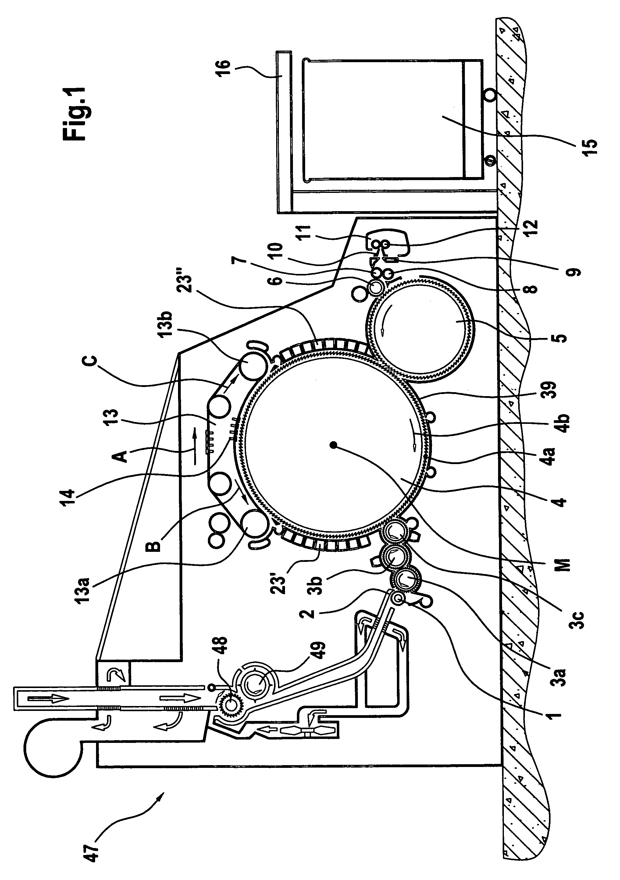
[0023]With reference to FIG. 1, a flat card, for example a TC 03 (Trademark) flat card made by Trützschler GmbH & Co. KG of Mönchengladbach, Germany, has a feed roller 1, feed table 2, lickers-in 3a, 3b, 3c, cylinder 4, doffer 5, stripper roller 6, nip rollers 7, 8, web-guiding element 9, web funnel 10, draw-off rollers 11, 12, revolving card top 13 having card-top-deflecting rollers 13a, 13b and card top bars 14, can 15 and can coiler 16. Curved arrows denote the directions of rotation of the rollers. Reference letter M denotes the centre (axis) of the cylinder 4. Reference numeral 4a denotes the clothing and reference numeral 4b denotes the direction of rotation of the cylinder 4. Reference letter B denotes the direction of rotation of the revolving card top 13 at the carding location and reference letter C denotes the direction in which the card top bars 14 are moved on the reverse side. Reference numerals 23′, 23″ denote stationary carding elements and reference numeral 39 denot...


PUM

PropertyMeasurementUnit
included angleaaaaaaaaaa

Abstract

A roller for a fibre-processing machine, for example a spinning preparation machine such as a flat card, cleaner or the like, flock feeder, roller card, nonwoven-forming machine or the like, comprises a roller body. In order to make possible, by simple means, economical manufacture and adequate dimensional stability, for example a substantially constant carding nip, the roller body has at least one metal cylinder and at least one circular cylindrical sheath of fibre-reinforced plastics material surrounding the cylinder.

Description

CROSS REFERENCE TO RELATED APPLICATION[0001]This application claims priority from German Patent Application No. 10 2004 035 770.6 dated Jul. 23, 2004, the entire disclosure of which is incorporated herein by reference.BACKGROUND OF THE INVENTION[0002]The invention relates to a roller for a fibre processing machine, for example a spinning preparation machine such as a flat card, cleaner or the like, flock feeder, roller card, nonwoven-forming machine or the like, having a wall of fibre-reinforced plastics material.[0003]The effective spacing of the tips of a clothing from a machine element located opposite the clothing is called a carding nip. The said machine element can also have a clothing but could, instead, be formed by an encasing segment having a guide surface. The carding nip is decisive for the carding quality. The size (width) of the carding nip is a fundamental machine parameter, which influences both the technology (the fibre processing) and also the running characteristi...

Claims


Application Information

Patent Timeline
Patent Type & Authority Patents(United States)
IPC IPC(8): D01G15/00D01G15/16
CPCD01G15/16F17C2209/2154D01G9/14D01G15/18D01G15/20
Inventor SCHLICHTER, STEFANVOLLRATH, ULRICH
Owner TRUETZSCHLER GMBH & CO KG
Why Eureka
Try Eureka