Imaging reader with target proximity sensor

a technology of proximity sensor and image reader, which is applied in the field of image reader with target proximity sensor, can solve the problems of image not being reliably and successfully decoded and read, and power consumption is a major concern, so as to improve power consumption, reduce power consumption, and improve the effect of indicia detection speed and efficiency

Active Publication Date: 2009-10-06
SYMBOL TECH LLC
View PDF3 Cites 6 Cited by
  • Summary
  • Abstract
  • Description
  • Claims
  • Application Information

AI Technical Summary

Benefits of technology

[0011]The low level illumination light has just enough visibility and intensity to enable the imager to detect that indicia are located in the field of view in the working range. This low level illumination light is sufficiently dim so that it will not distract or bother people in the vicinity of the reader, and consumes correspondingly less electrical power. When the indicia are detected in the field of view and in the working range, the high level illumination light is generated to acquire the image of the indicia for decoding and reading. After a successful decoding and reading, the high level illumination light is discontinued, and the low level illumination light is generated to again assist the imager in detecting indicia.
[0014]To further improve on power consumption and to make the indicia detection more rapid and more efficient, the indicia detection may be based on analyzing only the outer peripheral marginal zones of the image captured by the imager. Rather than illuminating the entire field of view with the low level illumination light, the field of view is only illuminated at the outer marginal zones. This can, for example, be achieved by optically modifying the low level illumination light with an optical element such as an axicon. Since the central area of the field of view is not illuminated, power consumption is minimized.

Problems solved by technology

In the context of a point-of-transaction workstation where the operator swipes the symbol past the window, sometimes once, sometimes several times, and where the operator presents the symbol with an additional component of movement toward and away from a window, and in some cases where the symbols are transported on a moving conveyor past a window, the image of the symbol is blurred due to the relative motion between the symbol and the imager and, as a result, the image cannot be reliably and successfully decoded and read.
Also, power consumption is a major concern, especially in handheld readers powered by batteries, since the high-brightness illuminator is a major energy consumer.

Method used


Image

  • Imaging reader with target proximity sensor
  • Imaging reader with target proximity sensor
  • Imaging reader with target proximity sensor

Examples


Embodiment Construction

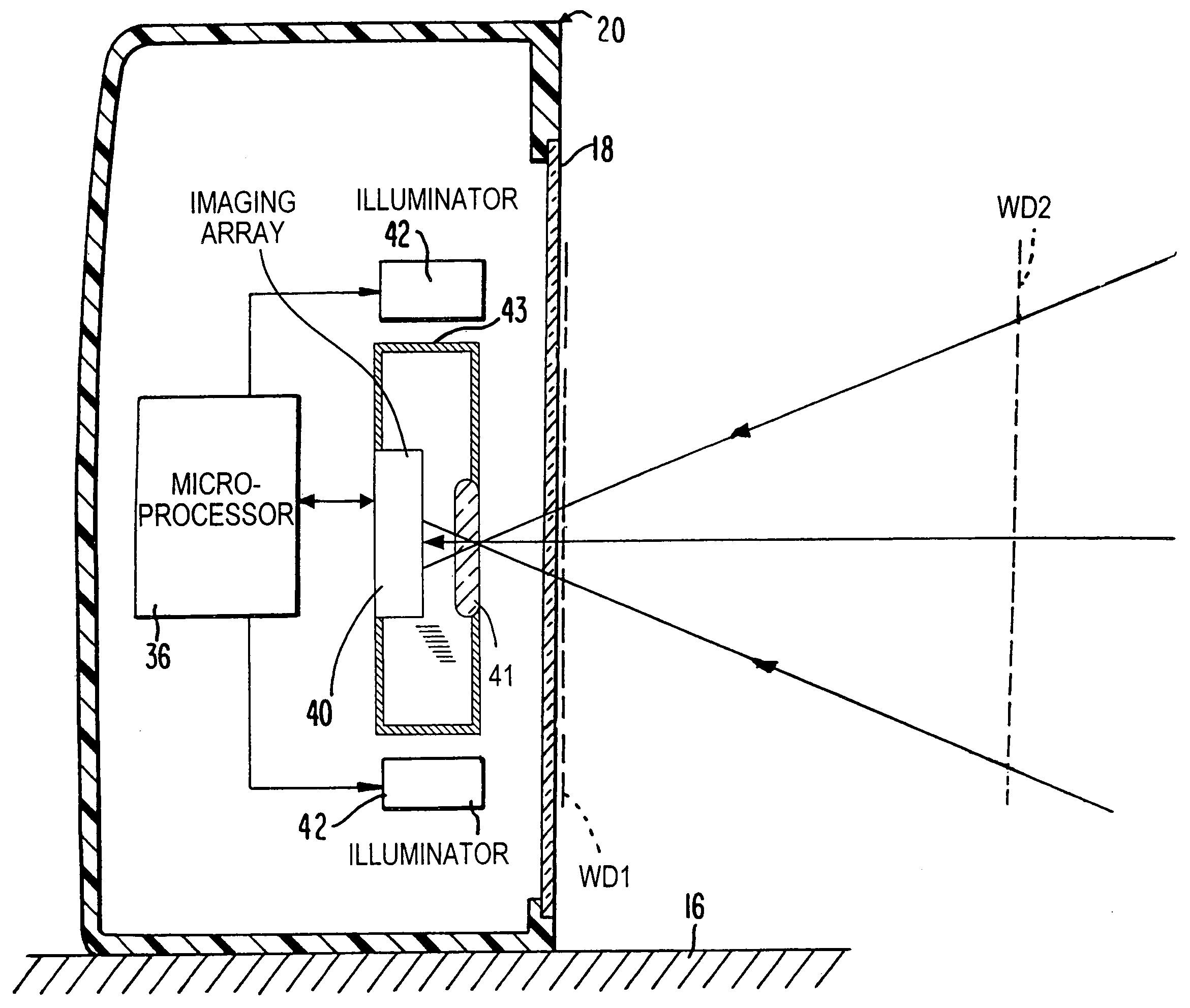
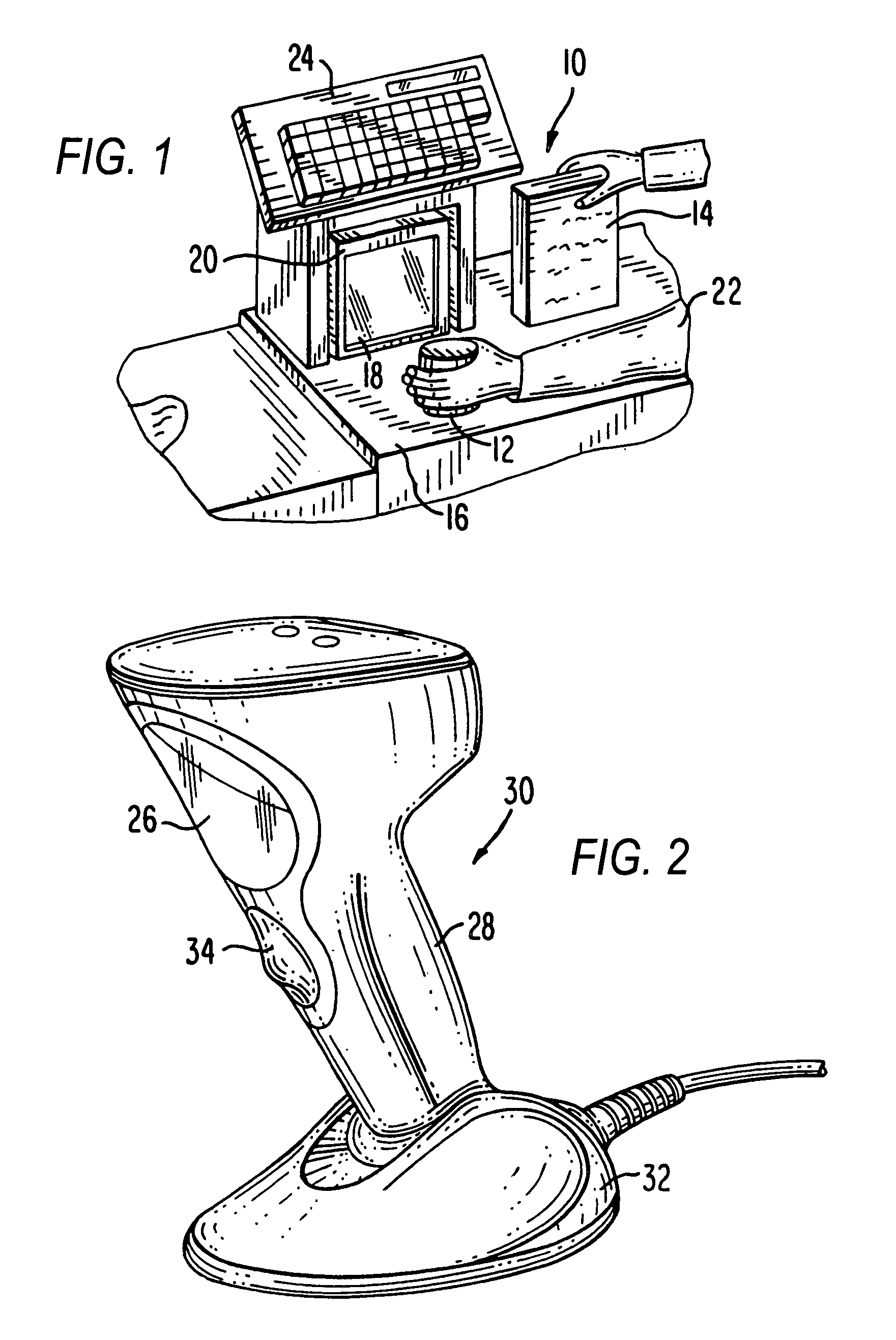
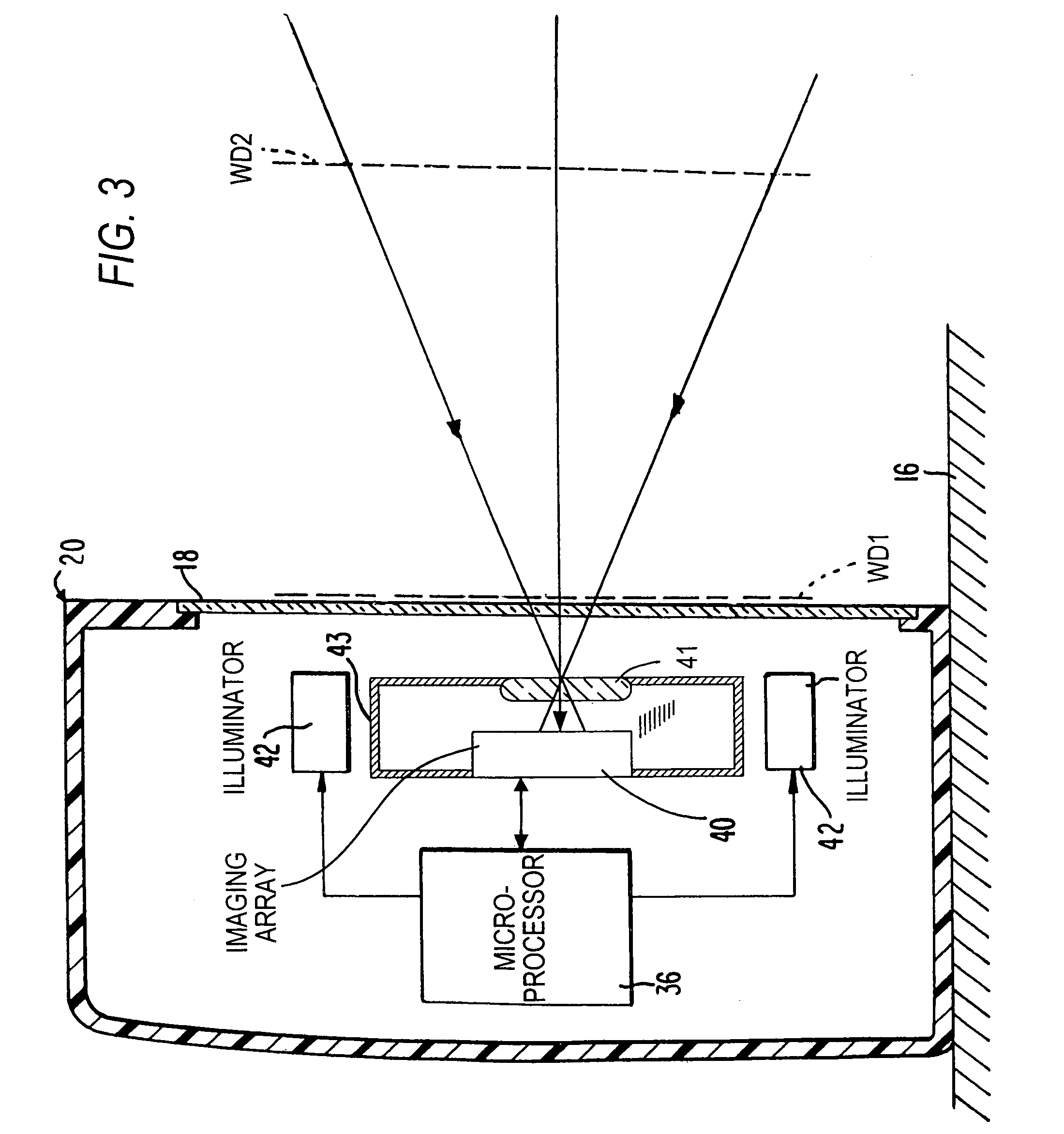
[0021]Reference numeral 10 in FIG. 1 generally identifies a workstation for processing transactions and specifically a checkout counter at a retail site at which products, such as a can 12 or a box 14, each bearing a target symbol, are processed for purchase. The counter includes a countertop 16 across which the products are slid at a swipe speed past a presentation area or vertical planar window 18 of a box-shaped vertical slot reader 20 mounted on the countertop 16. A checkout clerk or operator 22 is located at one side of the countertop, and the reader 20 is located at the opposite side. A cash / credit register 24 is located within easy reach of the operator.

[0022]Reference numeral 30 in FIG. 2 generally identifies another reader having a different configuration from that of reader 20. Reader 30 also has a presentation area or generally vertical window 26 and a gun-shaped housing 28 supported by a base 32 for supporting the reader 30 on a countertop. The reader 30 can thus be used...


PUM


Abstract

An illuminator illuminates a symbol with a low level of illumination in a detection mode of operation to enable an imager to detect the symbol in a working range and in a field of view of the imager in an imaging reader, and also illuminates the symbol with a high level of illumination in a reading mode of operation to enable the imager to read the symbol.

Description

DESCRIPTION OF THE RELATED ART[0001]Flat bed laser readers, also known as horizontal slot scanners, have been used to electro-optically read one-dimensional bar code symbols, particularly of the Universal Product Code (UPC) type, at a point-of-transaction workstation in supermarkets, warehouse clubs, department stores, and other kinds of retailers for many years. As exemplified by U.S. Pat. Nos. 5,059,779; 5,124,539 and U.S. Pat. No. 5,200,599, a single, horizontal window is set flush with, and built into, a horizontal countertop of the workstation. Products to be purchased bear an identifying symbol and are typically slid or swiped across the horizontal window through which a multitude of scan lines in a scan pattern is projected in a generally upward direction. Each scan line is generated by sweeping a laser beam from a laser. When at least one of the scan lines sweeps over a symbol associated with a product, the symbol is processed and read.[0002]Instead of, or in addition to, a ...

Claims


Application Information

Patent Timeline
Patent Type & Authority Patents(United States)
IPC IPC(8): G06K7/10
CPCG06K7/10722G06K7/10732G06K2207/1018
Inventor VINOGRADOV, IGORCARLSON, BRADLEY
Owner SYMBOL TECH LLC
Why Eureka
Try Eureka