Ink-jet apparatus and method of the same

a technology of ink jet and nozzle, which is applied in the direction of printing, other printing apparatus, etc., can solve the problems of high energy consumption of the pump, difficult liquid level control for the pressure reference, and inconspicuous ink pressure at the neighborhood of the nozzle opening

Active Publication Date: 2009-10-06
TOSHIBA TEC KK
View PDF11 Cites 44 Cited by
  • Summary
  • Abstract
  • Description
  • Claims
  • Application Information

AI Technical Summary

Problems solved by technology

The ink jet apparatus described in US 2002 / 0118256A1 has a problem that although the pressure of ink at the neighborhood of nozzle openings largely depends on channel resistance of the pipeline between an ink tank and the ink jet head, the pressure of ink at the neighborhood of the nozzle openings is not constant because no consideration is given to the channel resistance.
Liquid level control is difficult for the pressure reference.
Furthermore, there is a problem that since a large quantity of ink should be supplied to the pressure reference by a pump, the pump consumes much energy to operate.

Method used


Image

  • Ink-jet apparatus and method of the same
  • Ink-jet apparatus and method of the same
  • Ink-jet apparatus and method of the same

Examples


first embodiment

[1] FIRST EMBODIMENT

[0037]In the following, a first embodiment of the present invention will be described with reference to the drawings.

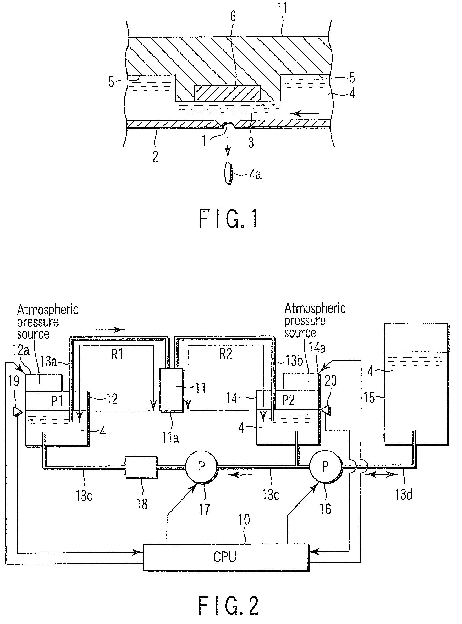
[0038]FIG. 1 shows a cross section of an ink jet head 11 of an ink circulating type. That is, a pressure chamber 3 is formed on a top surface side of an orifice plate 2 having a nozzle 1 for ejecting ink. Formed as a middle part of a channel 5 in the head which ink 4 runs through is narrowed, the pressure chamber 3 not only has the above-mentioned nozzle 1, but also has an actuator 6 on the surface side opposed to the nozzle 1. The ink 4 runs from right to left as shown in the figure, through the pressure chamber 3, in the channel 5 within the head.

[0039]As the actuator 6 is driven, the ink 4 within the pressure chamber 3 forms an ink droplet 4a and is ejected from the nozzle 1. As the actuator 6, those directly or indirectly transforming the pressure chamber 3 by use of a piezoelectric device such as a PZT are known. Furthermore, as the ink jet he...

second embodiment

[2] SECOND EMBODIMENT

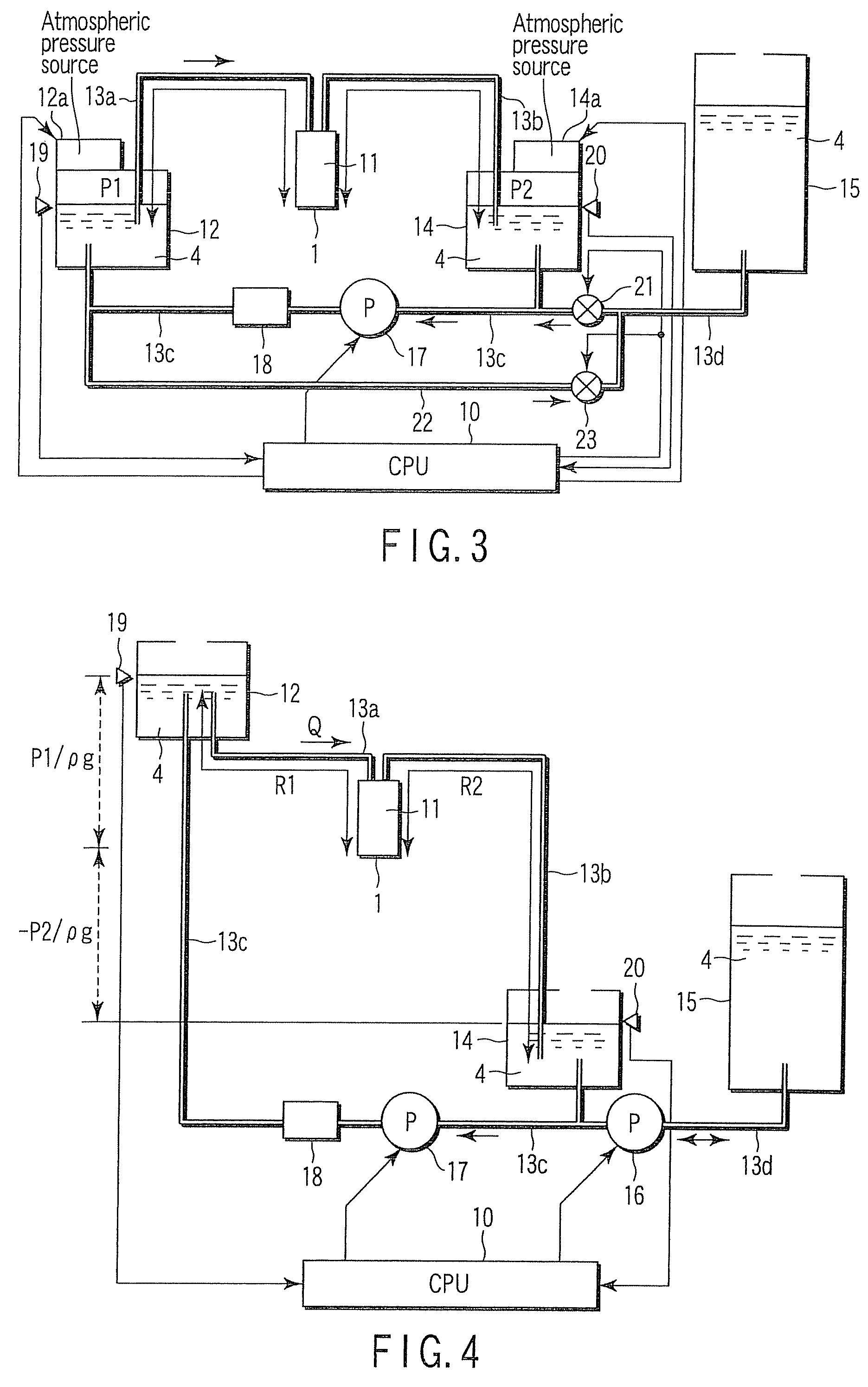
[0098]When ink 4 circulates in the direction from the first ink tank 12 through the head to the second tank 14, the condition P1>P2 exists. If the “energy per unit volume” of the ink 4 within the main tank 15 lies between the “energy per unit volume” P1 and “energy per unit volume” P2, the ink supply system can be simplified by adopting a fifth ink channel 22, a first valve 21, and a second valve 23 in place of the first pump 16, as shown in FIG. 3.

[0099]The fifth ink channel 22 is provided between a region on the side closer to the first ink tank 12 of the third ink channel 13c and the fourth ink channel 13d.

[0100]The connecting point of the fifth ink channel 22 and the third ink channel 13c is provided in a location sufficiently close to the first ink tank 12. At this time, the “energy per unit volume” of the ink at the connecting point then can be considered as almost at P1.

[0101]The connecting point of the fifth ink channel 22 and the fourth ink channel 13d...

third embodiment

[3] THIRD EMBODIMENT

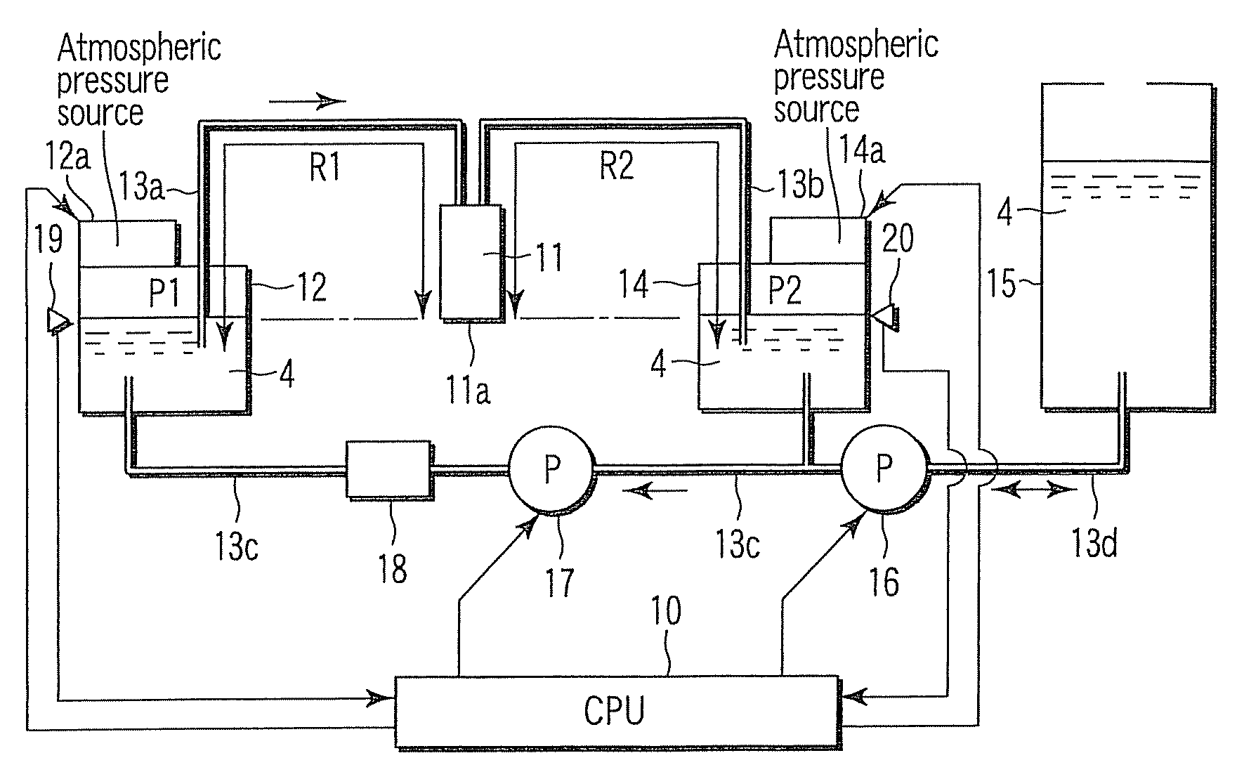
[0112]As shown in FIG. 4, as a first pressure source, a first ink tank 12 that contains the ink 4 supplied to a pressure chamber 3 of an ink jet head 11 and that is opened to the atmosphere has been adopted. This first ink tank 12 is arranged at a higher position than an opening of a nozzle 1 of the ink jet head 11. The “energy per unit volume” P1 generated in the ink 4 of the liquid level of the first ink tank 12 is only the potential pressure, and is defined according to a height position of the liquid level of the ink 4 within the first ink tank 12 that is based on the height position of the opening of the nozzle 1. “P1 / (ρ·g)” in FIG. 4 is this potential head (m).

[0113]As a second pressure source, a second ink tank 14 that contains the ink 4 flowing out from the pressure chamber 3 of the ink jet head 11 and that is opened to the atmosphere has been adopted. This second ink tank 14 is arranged at a position lower than the opening of the nozzle 1 of the ink jet ...


PUM


Abstract

“Energy per unit volume” P2(Pa) generated in ink 4 in a second ink tank 14 is maintained to the condition “P2={(1+r)×Pn}−(r×P1)” based on “energy per unit volume” P1(Pa) generated in ink 4 in the first ink tank 12, a proportion of “1:r” between channel resistance R1 (Pa·sec / m3) of ink from the first ink tank 12 to the neighborhood of a nozzle 1 and channel resistance R2 (Pa·sec / m3) of ink from the neighborhood of the nozzle 1 to the second ink tank 14, and appropriate pressure Pn (Pa) of the ink 4 in the neighborhood of the nozzle 1.

Description

CROSS-REFERENCE TO RELATED APPLICATIONS[0001]This application is based upon and claims the benefit of priority from the prior Japanese Patent Application No. 2006-123927, filed Apr. 27, 2006, the entire contents of which are incorporated herein by reference.BACKGROUND OF THE INVENTION[0002]1. Field of the Invention[0003]The present invention relates to an ink jet apparatus that circulates ink through an ink jet head and ejects ink from nozzles of the ink jet head, and a control method thereof.[0004]2. Description of the Related Art[0005]Conventionally, the ink jet apparatus that circulates ink through an ink jet head and ejects ink from nozzles of the ink jet head has been known. For example, there are the ink jet apparatuses described in US 2002 / 0118256A1 and US 2005 / 0007399A1.[0006]It is important for such an ink jet apparatus that the pressure of ink at the neighborhood of nozzle openings of the ink jet head should be always maintained at a constant level.[0007]The ink jet appara...

Claims


Application Information

Patent Timeline
Patent Type & Authority Patents(United States)
IPC IPC(8): B41J2/18
CPCB41J2/175B41J2/17509B41J29/377B41J2/17566B41J2/17596B41J2/17556
Inventor NITTA, NOBORUSHIMOSATO, MASASHINISHIDA, HIDEAKISUZUKI, ISAO
Owner TOSHIBA TEC KK
Why Eureka
Try Eureka