
Compact flashlight

a flashlight and compact technology, applied in the field of compact flashlights, can solve the problems of not being particularly well adapted for use, prone to overlooking certain operating or human factors, and long fingernails affecting the housing, so as to prevent accidental actuation of the switch, facilitate one-handed operation, and facilitate the effect of unintentional activation

Inactive Publication Date: 2009-10-20
BRITE STRIKE TECH
View PDF4 Cites 25 Cited by
  • Summary
  • Abstract
  • Description
  • Claims
  • Application Information

AI Technical Summary

Benefits of technology

"The patent text describes a compact flashlight designed for women and children who prefer smaller and lighter flashlights. The flashlight has a unique design that prevents interference from long fingernails and accidental activation of the switch. The design includes a clearance for fingernails and an end cap switch with a rim to prevent accidental activation. The flashlight is ergonomically designed for easy and comfortable one-handed operation. The technical effects of the patent text are improved operability and protection of the switch from unintended or accidental activation, especially for users with long fingernails."

Problems solved by technology

Many of the commercially-available self defense or tactical flashlights adapted for civilian use are intentionally large, bulky and heavy so that they can also be used as a club for striking in self defense.
While these flashlights work well, they are not particularly well adapted for use by women and children who tend to prefer smaller and lighter flashlights.
Although some flashlights have been designed with reduced size and weight, they tend to overlook certain operating or human factors that are common to women.
It has been found that long fingernails tend to interfere with the housings surrounding on-off switches of the type used in self defense and tactical flashlights.
This interference is a particular problem on flashlights having rear end-cap switches which are bordered or surrounded by a rim.
This can prevent proper operation of the switch and result in a damaged fingernail.
Although some flashlight end cap switches project rearwardly and outwardly from the end cap, these exposed switches are easily activated unintentionally when bumped or dropped.
This can unknowningly turn on the flashlight and drain the battery or batteries.

Method used


Image

  • Compact flashlight
  • Compact flashlight
  • Compact flashlight

Examples


Embodiment Construction

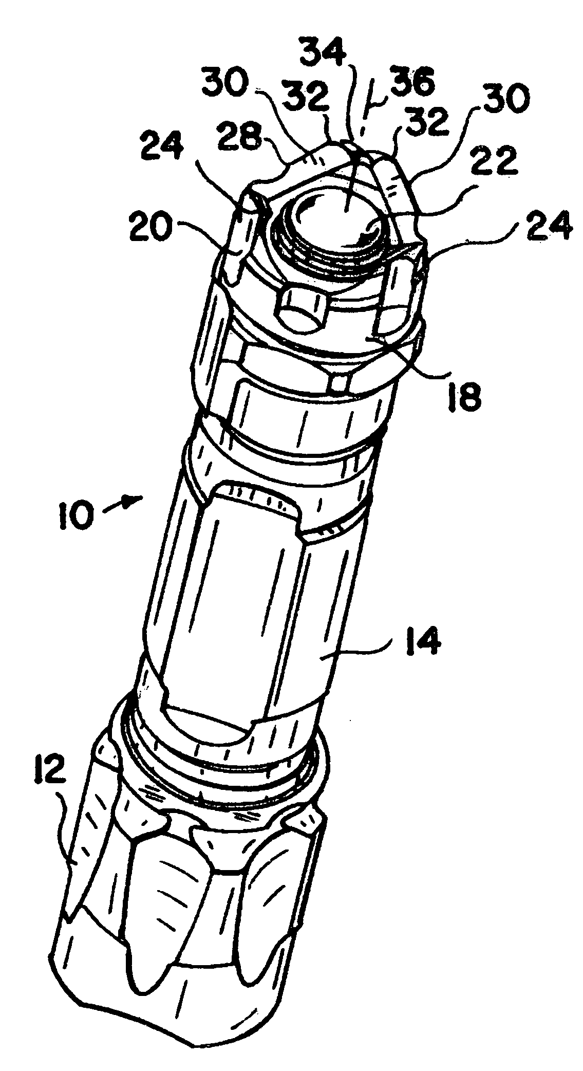
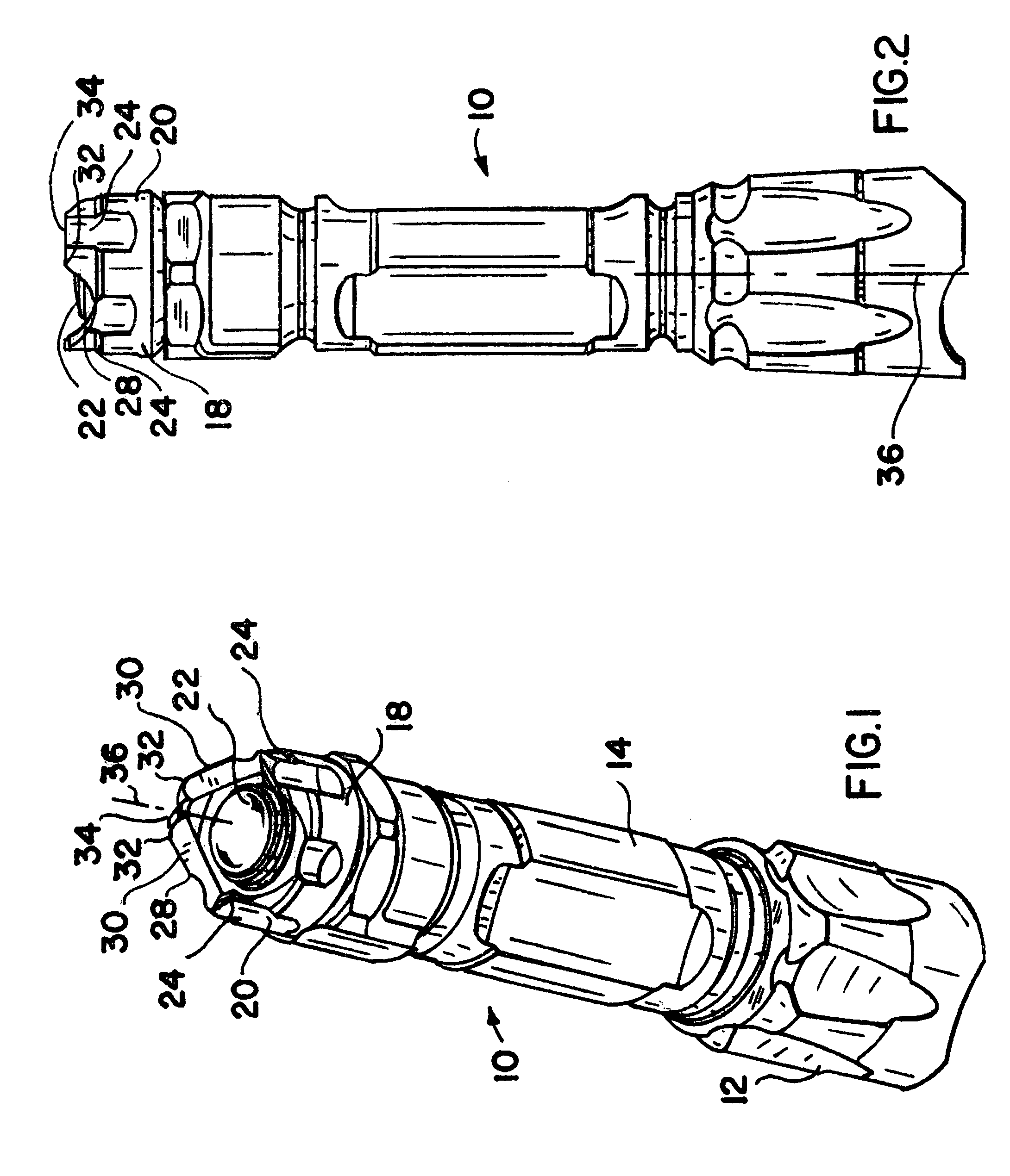
[0015]A flashlight 10 shown in FIG. 1 includes a removable front crown 12 surrounding an axially-recessed lens covering a high intensity light-emitting-diode which provides an intense beam of light. The flashlight 10 further includes a tubular body 14 for housing one or more disposable or rechargeable batteries. A removable rear end cap 18 is threaded to the rear end of the tubular body 14.

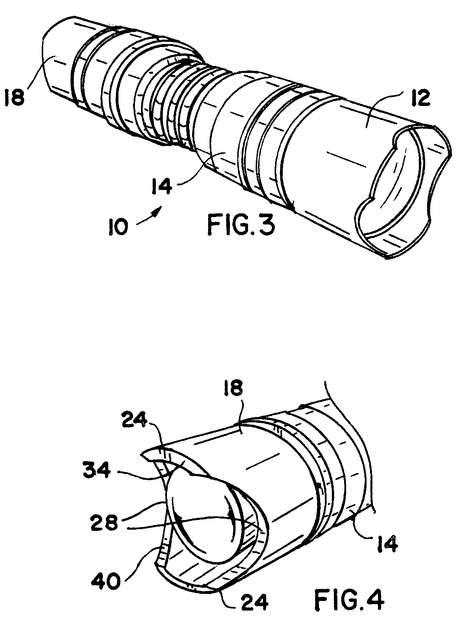
[0016]The end cap 18 includes a sidewall 20 that surrounds a user-operated switch actuator 22 which is operated by movement along flashlight axis 36. As seen in FIGS. 1 and 2, the sidewall 20 is formed with three axially-rearwardly extending wall portions 24 which are symmetrically and circumferentially separated and spaced apart by three recesses, grooves or axial cut-out portions 28.

[0017]The grooves 28 in FIGS. 1 and 2 are formed as shallow U-shaped arcuate cuts or openings in the sidewall 20. The edges 30 of each groove 28 are formed as sharp chisel edges for use in self defense. The top of ea...


PUM


Abstract

A flashlight is provided with an end cap which carries an axially-actuated switch for turning the flashlight on and off with a convenient one-handed operation. The switch is designed with a latching function and a mode selection function which can be cycled through high, low and strobed light outputs with a partial throw of the switch. Cut-out portions are provided in the end cap for guiding a user's finger toward the switch and away from the sidewalls of the end cap.

Description

CROSS REFERENCE TO RELATED APPLICATIONS[0001]This application claims the benefit and priority of provisional patent application No. 60 / 931,437 filed May 23, 2007, entitled Tactical Flashlight, and which is incorporated herein by reference in its entirety.BACKGROUND AND SUMMARY[0002]High intensity flashlights are commonly carried by police and other law enforcement agents to aid in illuminating dark locations and to serve as a form of self defense. A bright intense light can temporarily stun or disorient an attacker when the light is directed at the attacker's eyes. Civilian versions of these flashlights are currently available in various shapes and sizes.[0003]Many of the commercially-available self defense or tactical flashlights adapted for civilian use are intentionally large, bulky and heavy so that they can also be used as a club for striking in self defense. While these flashlights work well, they are not particularly well adapted for use by women and children who tend to pref...

Claims


Application Information

Patent Timeline
Patent Type & Authority Patents(United States)
IPC IPC(8): F21L4/04
CPCA62B3/005F41B15/08F41B15/00F21V33/0076F21L4/027F21Y2101/02Y10S362/802F21Y2115/10
Inventor BUSHEE, GLENNNEAL, JONATHAN
Owner BRITE STRIKE TECH
Learn More