Cable connector assembly having improved fixing member

a technology of fixing member and connector, which is applied in the direction of coupling prevention, substation/switching arrangement details, coupling device connections, etc., can solve the problem that the engagement between the screw and the screw cap is not reliable enough for fastening the panel onto the first housing

Inactive Publication Date: 2009-10-27
HON HAI PRECISION IND CO LTD
View PDF14 Cites 30 Cited by
  • Summary
  • Abstract
  • Description
  • Claims
  • Application Information

AI Technical Summary

Benefits of technology

The present invention is a cable connector assembly with a better fixing member that can reliably fix things up.

Problems solved by technology

The technical problem addressed in this patent text is the need for an improved fixing member for a cable connector assembly, as the current method of using screws and screw caps is not reliable enough for fastening a panel onto the housing.

Method used


Image

  • Cable connector assembly having improved fixing member
  • Cable connector assembly having improved fixing member
  • Cable connector assembly having improved fixing member

Examples


Embodiment Construction

[0020]Reference will now be made in detail to the preferred embodiment of the present invention.

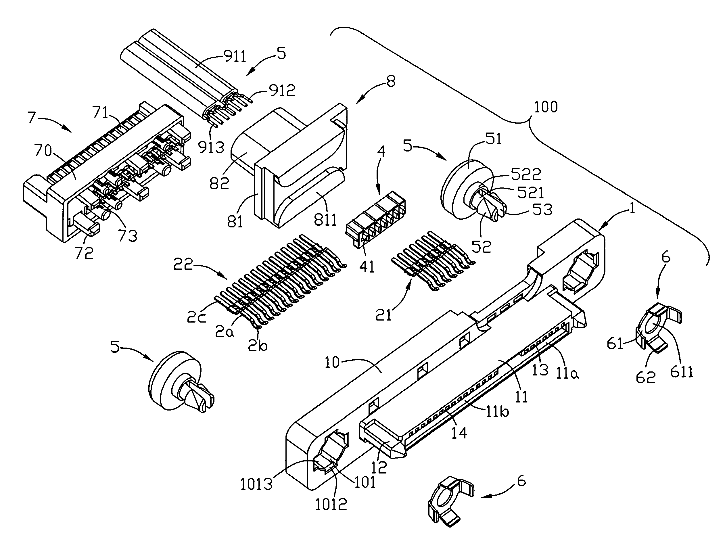
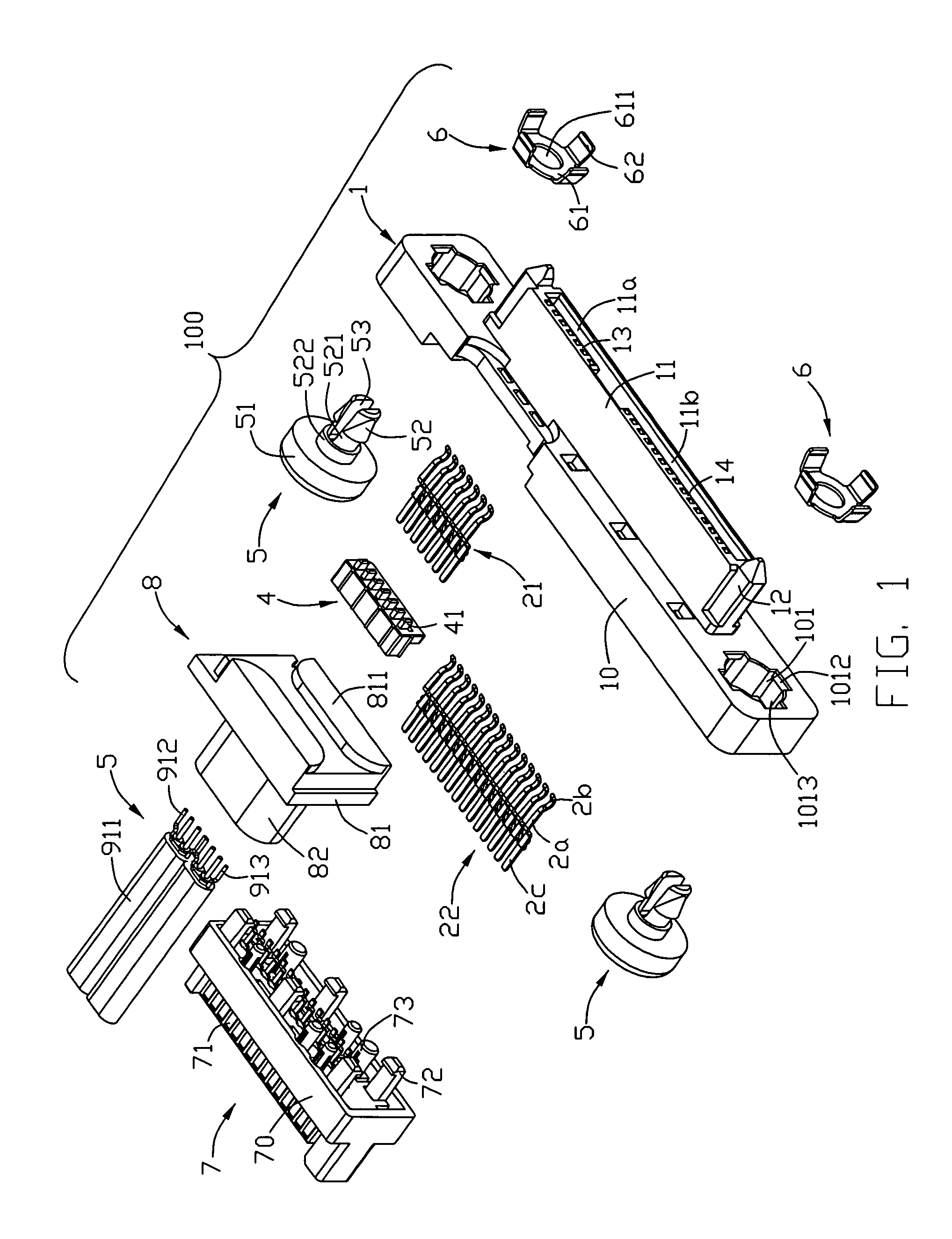
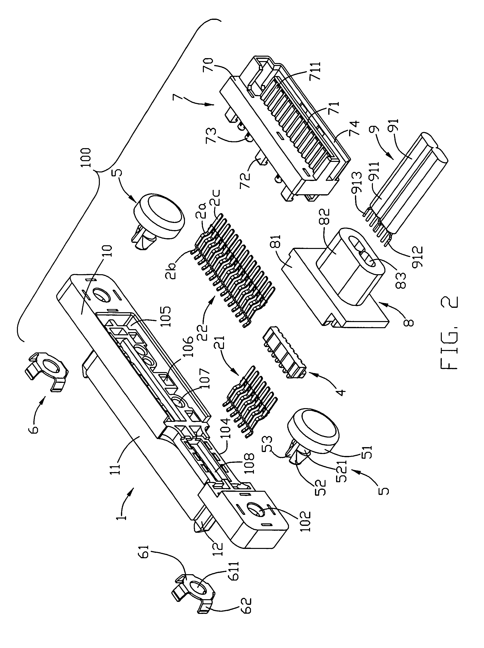
[0021]Referring to FIGS. 1-4 and 8, a cable connector assembly 100 adapted for mating with a panel 300 in accordance with the present invention comprises a first housing 1, a plurality of terminals, a retention portion 4 retained in the first housing 1, a second housing 7 assembled to the first housing 1, a cable 9 connected to the first housing 1 via a connecting portion 8, a pair of screws 5 and a pair of screw caps 6 engaging with the screws 5. The screw 5 and the corresponding screw cap 6 are cooperated as a fixing member.

[0022]The first housing 1 has an elongated base portion 10 and a mating portion 11 extending perpendicularly and forwardly from a front face of the base portion 10. The mating portion 11 has a pair of protruding posts 12 disposed at opposite ends thereof for guiding the cable connector assembly 1 to mate with a complementary connector (not shown) along a mating direc...


PUM


Abstract

A cable connector assembly (100) is assembled to a panel (300) defining a pair of insertion holes (32). The cable connector assembly includes a first housing (1), a number of first and second terminals (21, 22) assembled to the first housing, a cable (9), a second housing (7) assembled to the first housing, and a pair of fixing members. The first housing has a pair of mounting holes defined at opposite sides thereof. Each fixing member includes a screw (5) defining a screw recess (521) engageable with the insertion hole of the panel, and a screw cap (6) including a gasket (61) defining a through hole (611) engageable with the screw recess of the screw and a number of tabs (62) radially protruding from the gasket and resisting against the mounting hole.

Description


Claims


Application Information

Patent Timeline
Owner HON HAI PRECISION IND CO LTD
Why Eureka
Try Eureka