Fiber attractor and attachment apparatus for increasing the attracting tendencies of fishing lures

a technology of lures and attractors, applied in the field of fishing lures, can solve problems such as unsolved problems

Inactive Publication Date: 2010-02-09
AVERY RONALD ALLEN
View PDF93 Cites 34 Cited by
  • Summary
  • Abstract
  • Description
  • Claims
  • Application Information

AI Technical Summary

Problems solved by technology

The fishing lures identified in the search leave several problems unsolved.

Method used


Image

  • Fiber attractor and attachment apparatus for increasing the attracting tendencies of fishing lures
  • Fiber attractor and attachment apparatus for increasing the attracting tendencies of fishing lures
  • Fiber attractor and attachment apparatus for increasing the attracting tendencies of fishing lures

Examples


Embodiment Construction

)

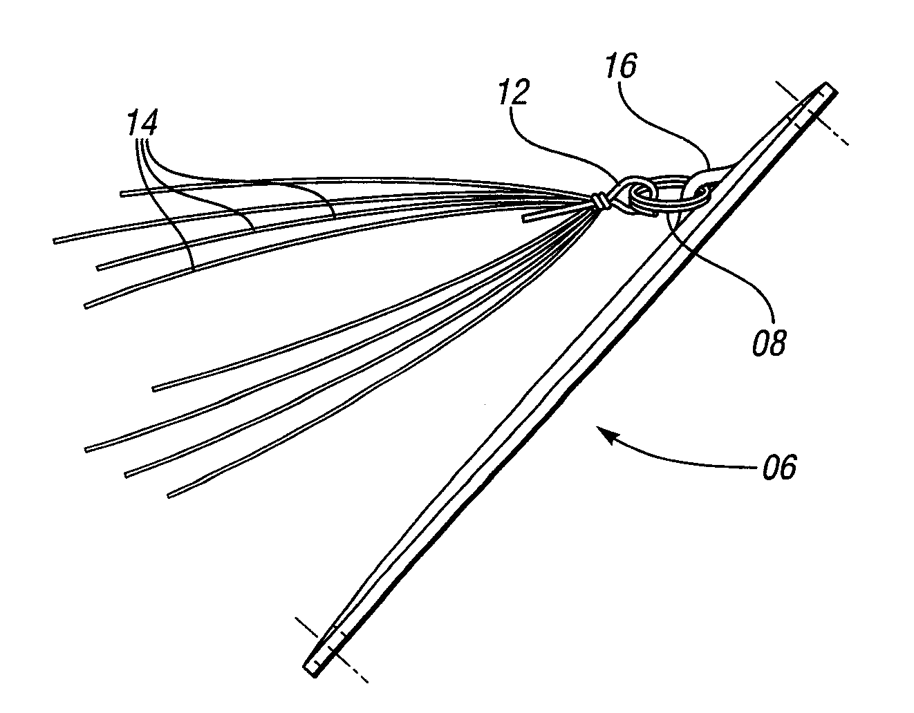
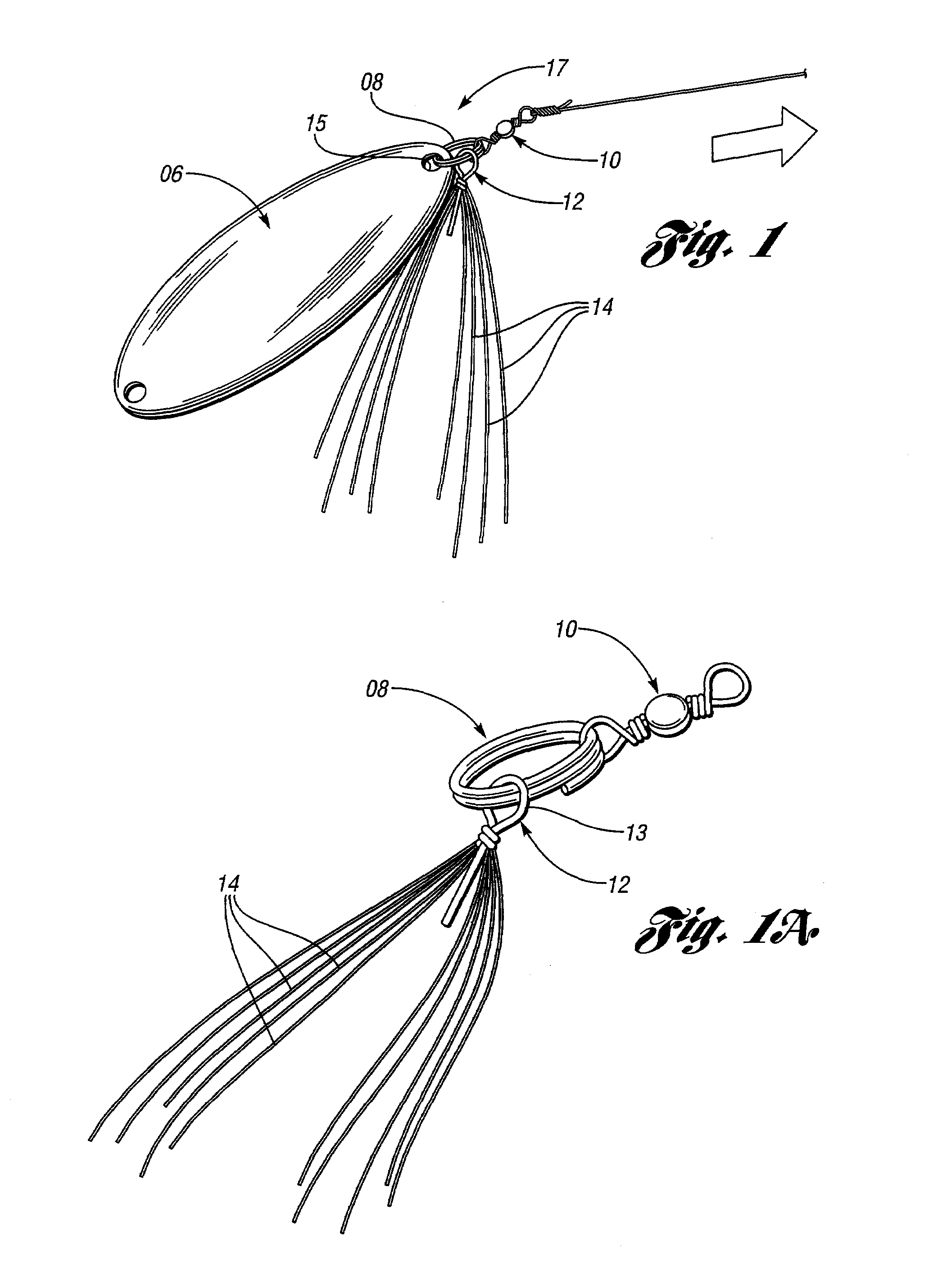
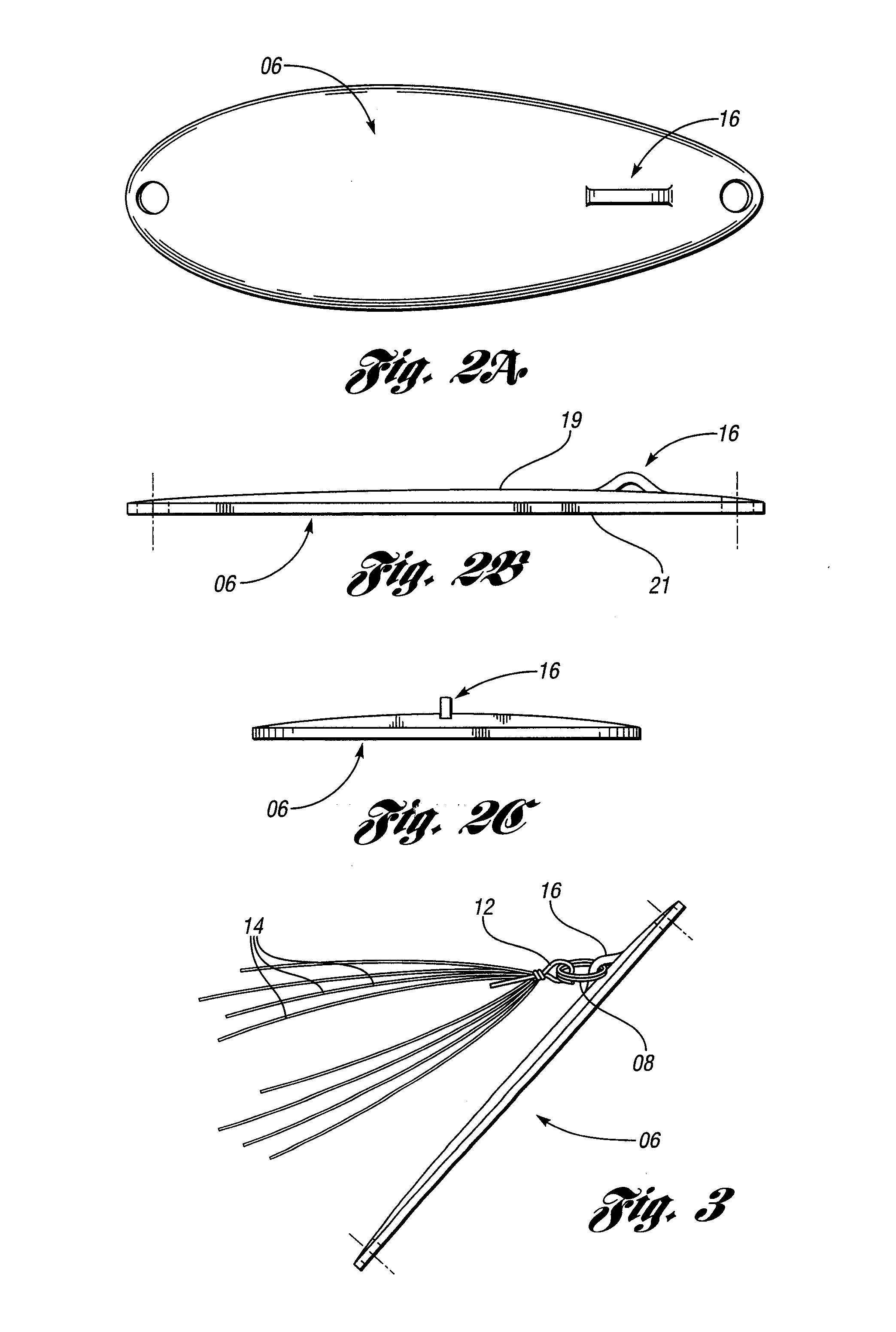
[0020]Referring to FIGS. 1 through 4 of the drawings, there are depicted several components of a fishing lure assembly. Components of the assembly include a fishing lure 6 and an attachable subassembly that includes in one embodiment (1) a metal ring 8; (2) a barrel or crane swivel 10 that connects the ring 8 to a fishing line; (3) a shaft 12; and attracting fibers or fronds 14 that are secured to the shaft 12.

[0021]FIG. 1A depicts one embodiment of the subassembly. The shaft 12 is provided in that embodiment with an eye 13 that is engageable with the ring 8. Optionally, fibers 14 can be secured to the eye 13 or shaft 12. The swivel 10 allows for rotation of the sub-assembly about an axis imaginarily defined by a direction of forward propulsion in response to a pulling force exerted by the fishing line.

[0022]As illustrated, the metal ring 8 may be in the form of a welded or split ring. That subassembly in some embodiments is connected by the metal ring 8 to a forward hole 15 which ...


PUM


Abstract

A fishing lure combination having a spoon 6 with a leading region 17, a disturbance-creating attachment lug 16 extending from a surface 19 associated with the leading region 17, and trailing fronds 14 that are secured via a shaft 12 to the attachment lug 16. The trailing fronds 14 are agitated by turbulent fluid flow downstream of the attachment lug 16.

Description

CROSS-REFERENCE TO RELATED APPLICATIONS[0001]This application is a non-provisional application based on prior provisional patent application No. 60 / 815,306, filed on Jun. 20, 2006. The disclosure of that application is incorporated herein by reference.BACKGROUND OF THE INVENTION[0002]1. Field of the Invention[0003]This invention relates generally to fishing lures and more specifically to a fishing lure that has the characteristics of an enhanced attracting tendencies.[0004]2. Background Art[0005]In the context of sport fishing, a lure is an object that is attached to the end of a fishing line. The lure is designed to resemble and move like a specimen of fish prey. Conventionally, many lures are equipped with one or more hooks with which to engage to fish when the fish attacks the lure. Typically, motion is imparted to lures by winding a line back on a reel, by sweeping, jiggling movements with an apparatus such as a fishing rod or by being pulled behind a moving boat (“trolling”). W...

Claims


Application Information

Patent Timeline
Patent Type & Authority Patents(United States)
IPC IPC(8): A01K85/00A01K85/14
CPCA01K85/00A01K85/14
Inventor AVERY, RONALD ALLEN
Owner AVERY RONALD ALLEN
Why Eureka
Try Eureka