


Quick Research
Generate reliable direction feasibility study reports for your R&D in just a few steps.

Technical Q&A
Discover and master advanced knowledge NOW. Basics, ideas, possibilities, all at once.

Find Solutions
As an expert in R&D theories, this can generate solutions to your technical problems instantly.

Evaluate Feasibility
Analyze your overall solution with one click, know your potential R&D risks in advance.

Monitor Landscape
Get weekly tech updates, stay abreast of the latest tech innovations and key insights.
Electrically actuated aircraft brakes
a technology of aircraft brakes and actuators, applied in the direction of actuators, brake actuating mechanisms, axially engaging brakes, etc., can solve the problems of inability to rely, several problems to be overcome, and inability to evaluate the remaining cycle to overhaul
- Summary
- Abstract
- Description
- Claims
- Application Information
AI Technical Summary
Benefits of technology
Problems solved by technology
Method used
Image

Examples
Embodiment Construction
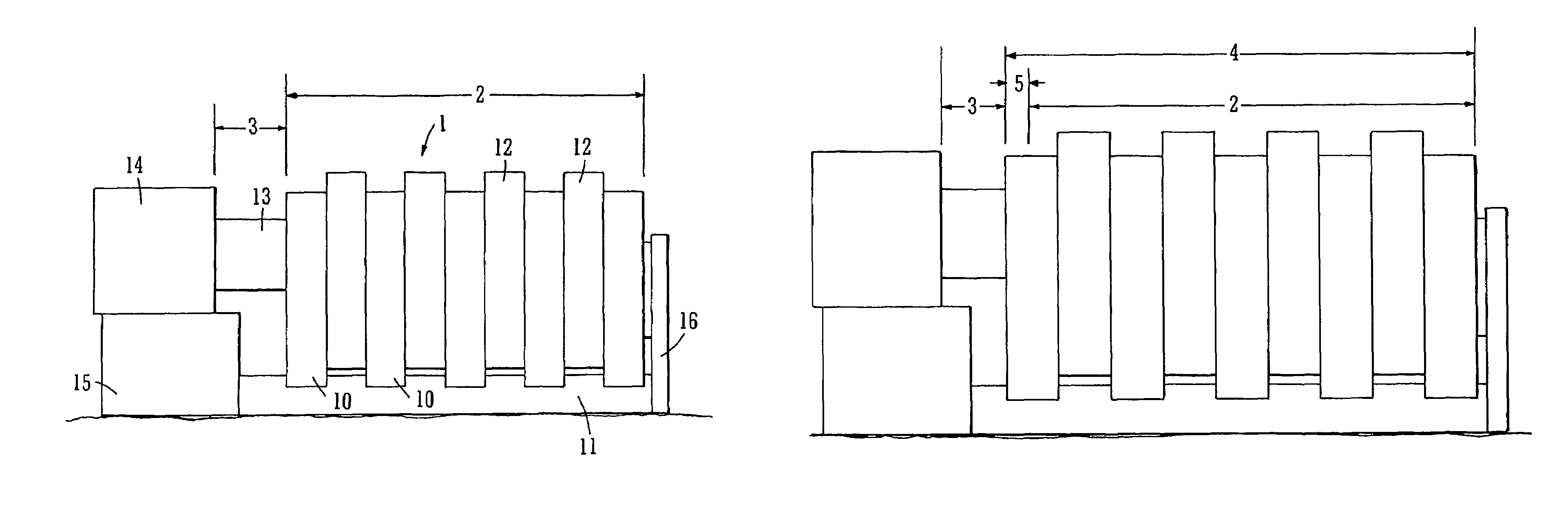
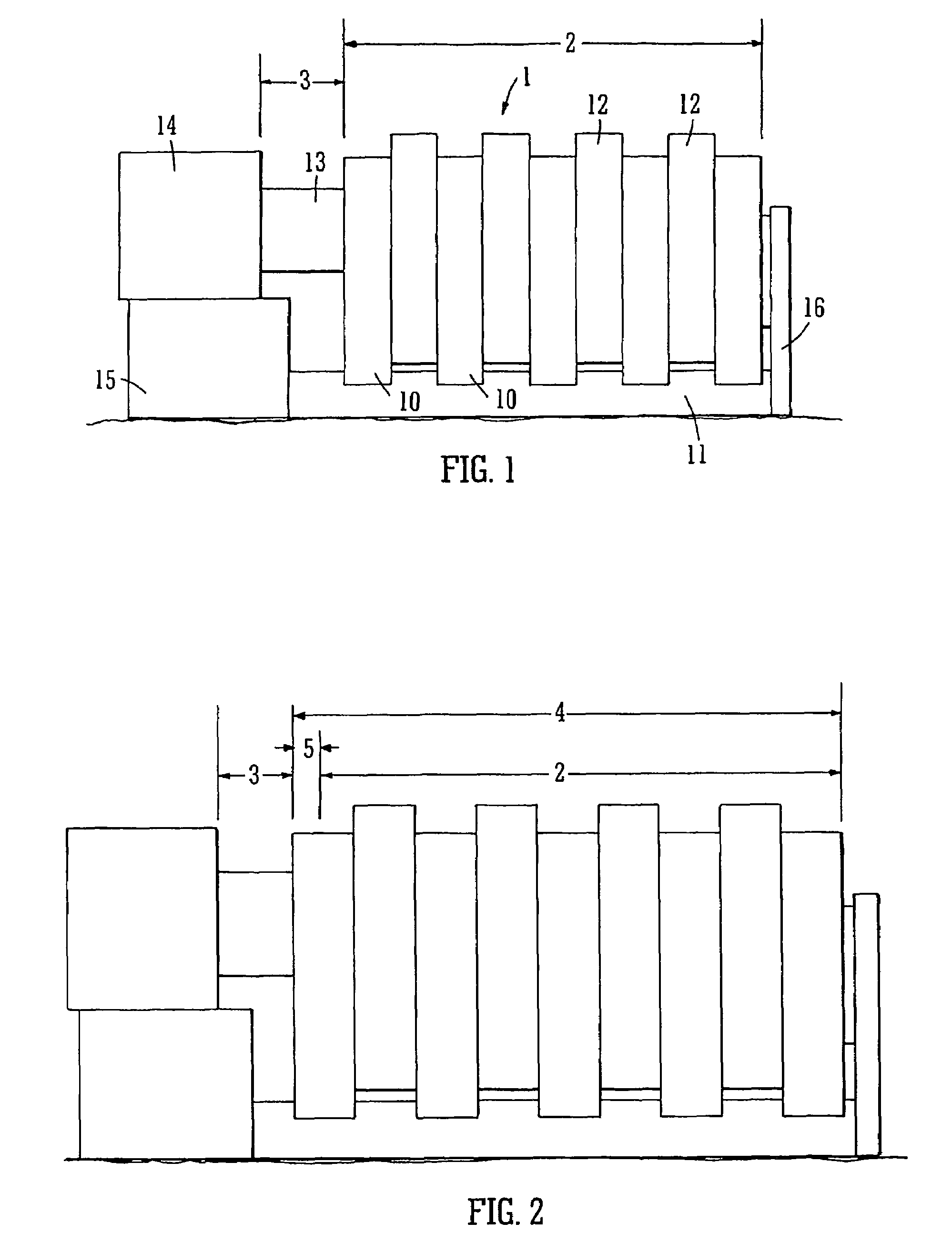
[0047]FIG. 1 represents a section of a brake assembly comprising a brake heat pack 1 comprising a plurality of carbon-carbon composite stator discs 10 keyed to a torque tube 11 and axially mounted about a wheel axle (not shown). Interleaved between the stator discs are a corresponding number of rotor discs 12 keyed to the inside of a wheel (not shown) for rotation with the wheel. The stator and rotor discs in the brake heat pack are brought into frictional engagement by the application of the braking load by a plurality of actuator rams 13 which are arrayed around the wheel axis but only one of which is visible in the figure. Each ram 13 is driven by a motor (not shown) through a gear and ball screw mechanism (not shown) housed within a respective electrically powered actuator module body 14. The plurality of actuator modules 14 are mounted around a brake plate 15 to which the torque tube is attached. The brake plate is non-rotatably mounted to the aircraft landing gear (not shown)....
PUM
 Abstract
Description
Claims
Application Information
 - R&D Engineer
- R&D Manager
- IP Professional
- Industry Leading Data Capabilities
- Powerful AI technology
- Patent DNA Extraction
Browse by: Latest US Patents, China's latest patents, Technical Efficacy Thesaurus, Application Domain, Technology Topic, Popular Technical Reports.
© 2024 PatSnap. All rights reserved.Legal|Privacy policy|Modern Slavery Act Transparency Statement|Sitemap|About US| Contact US: help@patsnap.com