Interlocking precision flexible rail system

a flexible rail system and precision technology, applied in the direction of metal-working apparatus, ways, constructions, etc., can solve the problems of inability to interchange the rail set, the splicing is difficult to achieve, and the precision flexible rail system for tool positioning is difficult to make and handle in long lengths

Active Publication Date: 2010-03-16
THE BOEING CO
View PDF31 Cites 16 Cited by
  • Summary
  • Abstract
  • Description
  • Claims
  • Application Information

AI Technical Summary

Benefits of technology

[0010]The present invention provides an interlocking precision flexible rail system for carrying a positionable machine tool employing a first rail element having a first step on a lower surface extending from a first end to a termination at a predetermined length and a second rail element having a mating step on an upper surface extending from a second end to receive the first step. A pair of first clips is removably affixed to a top surface of the first rail element adjacent the first end with a first pin and to the second rail element with a second pin in each clip. A pair of second clips is removably affixed to a bottom surface of the second rail element adjacent the second end with a third pin and to the first rail element with a forth pin in each clip. The first and second pairs of clips and associated pins laterally secure the rail elements in mated engagement.

Problems solved by technology

However, precision flexible rail systems for tool positioning are difficult to make and handle in long lengths.
However, technical challenges arise in the splice.
While match drilling can make a straight joint, the end result is a non-interchangeable rail set.
Non interchangeability is highly undesirable and considered impractical in most manufacturing environments.
The key problem characteristics are the difficulty in making straight rail splices that are interchangeable and maintain the flex characteristics of a flexible rail
Unfortunately they all fall short of that goal.
Previous devices such as short metal sandwiching clips are too short in length to achieve interchangeability and repeatable accuracy at the same time.
This stiffness can cause significant flat spots when the rail is flexed to a work piece contour

Method used


Image

  • Interlocking precision flexible rail system
  • Interlocking precision flexible rail system
  • Interlocking precision flexible rail system

Examples


Embodiment Construction

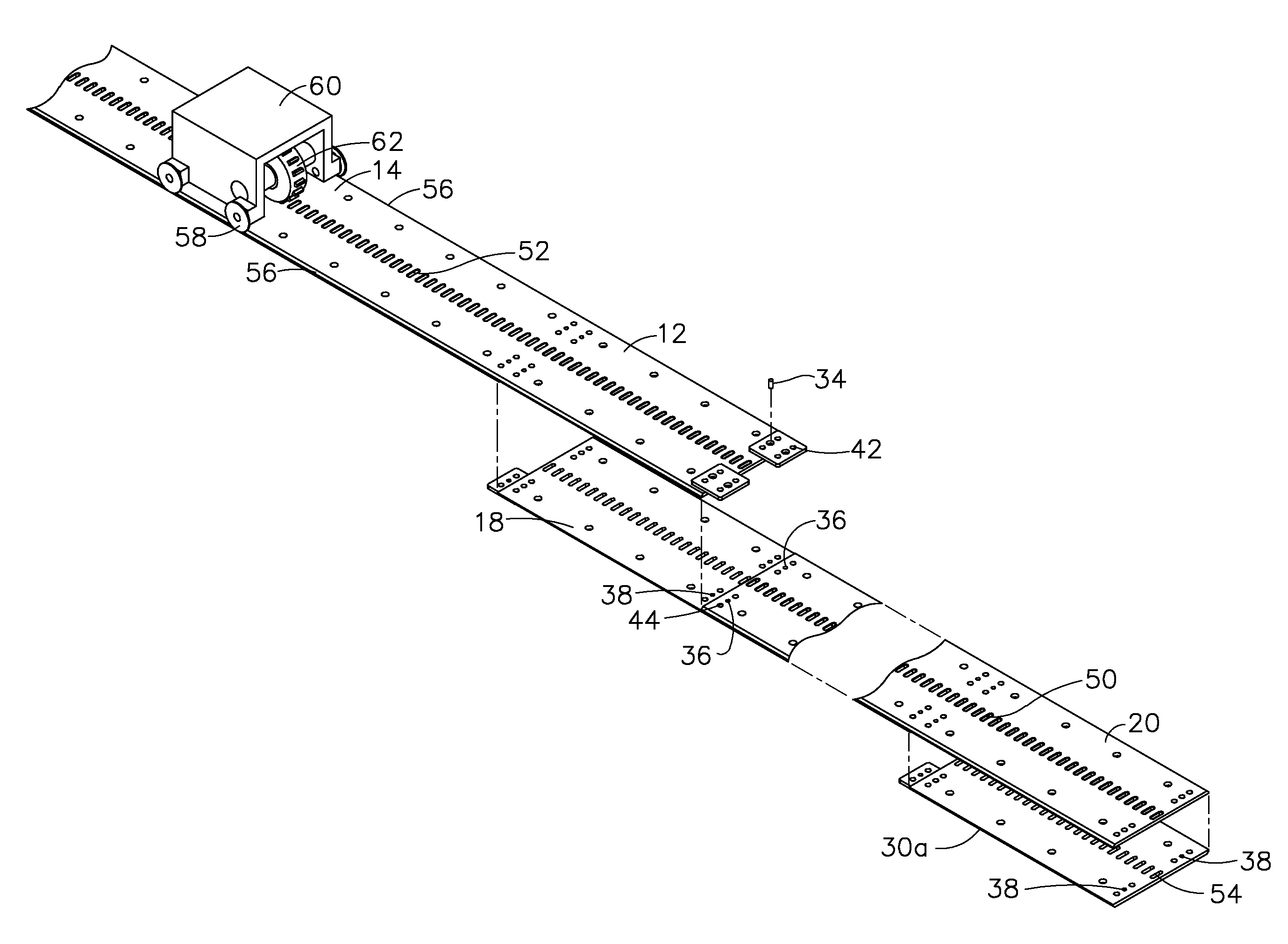
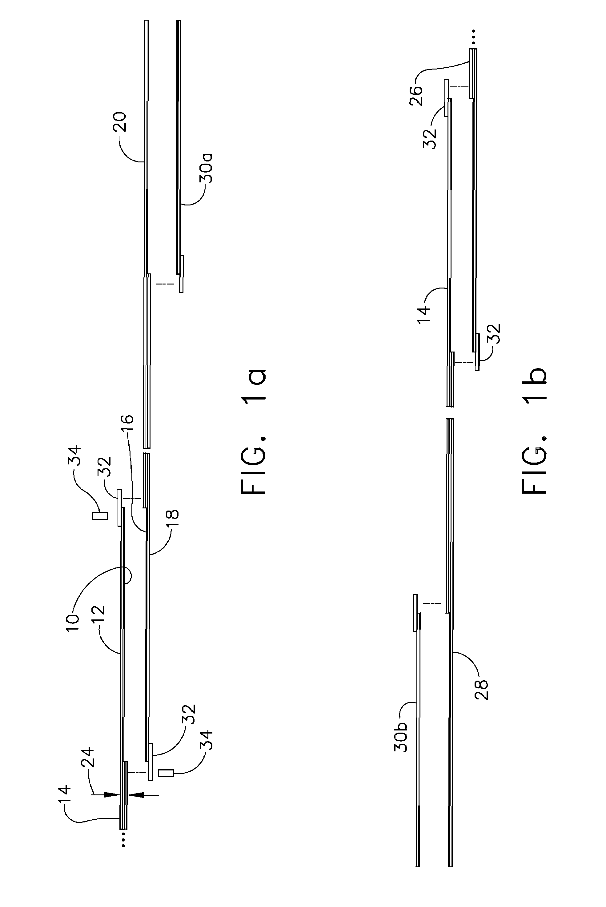
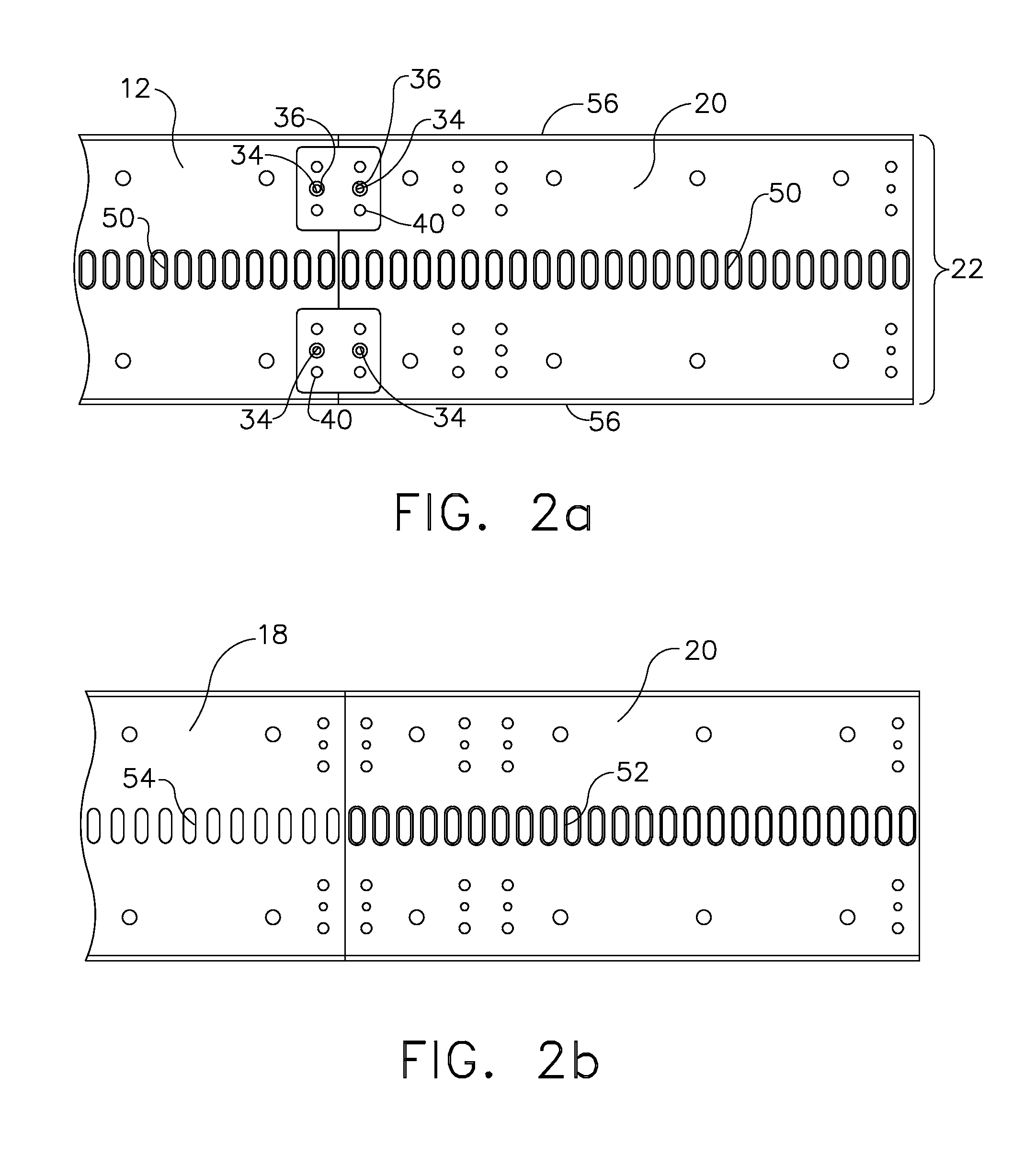
[0017]This invention achieves the three most desired traits in a precise-flex-rail splice. First it achieves a straight joint because it is made of relatively long stepped overlaps. Second it achieves interchangeability because the alignment pins are separated by far enough distance that reasonable clearance can be used for assembly. Third, the stepped rail with short splice clips at each end does not compromise rail flexibility at the joint. As shown in FIG. 1 an interlocking feature is provided by a step 10 that is machined into a first end 12 of a first length of precision flexible rail 14 and a mating step 16 in a mating end 18 of a second length 20 of a precise flexible rail. The step is machined to substantially a half thickness of the rail from the underside of the first length and the top side of the second length directly down the center line where no stress occurs during bending of the rail. The rail elements have a high aspect ratio of width 22 to thickness 24 to maintain...


PUM


Abstract

An interlocking precision flexible rail system for carrying a positionable machine tool employs a first rail element having a first step on a lower surface extending from a first end to a termination at a predetermined length and a second rail element having a mating step on an upper surface extending from a second end to receive the first step. A pair of first clips is removably affixed to a top surface of the first rail element adjacent the first end with a first pin and to the second rail element with a second pin in each clip. A pair of second clips is removably affixed to a bottom surface of the second rail element adjacent the second end with a third pin and to the first rail element with a forth pin in each clip. Alignment holes to receive the pins have tolerances defined in conjunction with the predetermined length of the step, the length of the step allowing a reduced tolerance. The first and second pairs of clips and associated pins laterally secure the rail elements in mated engagement.

Description

BACKGROUND OF THE INVENTION[0001]1. Field of the Invention[0002]This invention relates generally to the field of reconfigurable manufacturing tooling systems and more particularly to a flexible rail system for automatic positioning drill or tool systems which is unlimited in extension length and remains flexible over interlocking extensions.[0003]2. Description of the Related Art[0004]The use of automated positioning tooling systems for fabrication of large structural elements on aircraft and other large systems is prevalent in current manufacturing practice. However, precision flexible rail systems for tool positioning are difficult to make and handle in long lengths. To solve this problem rails are made in short lengths of 4 to 7 feet. To achieve a long rail the rails are simply spliced together. However, technical challenges arise in the splice. A typical splice tends to be crooked at the joint. While match drilling can make a straight joint, the end result is a non-interchangeab...

Claims


Application Information

Patent Timeline
Patent Type & Authority Patents(United States)
IPC IPC(8): E01B23/04
CPCB23Q9/0042B23Q2210/008
Inventor BOYL-DAVIS, THEODORE M.OUTOUS, RONALD W.
Owner THE BOEING CO
Why Eureka
Try Eureka