Throwing apparatus

a technology of throwing apparatus and sledgehammer, which is applied in the field of throwing apparatus, can solve the problems of increasing the difficulty of throwing

Inactive Publication Date: 2010-03-30
FITT CARL DOUGLAS +2
View PDF6 Cites 55 Cited by
  • Summary
  • Abstract
  • Description
  • Claims
  • Application Information

AI Technical Summary

Benefits of technology

[0005]It is therefore an object of the person invention to provide a throwing apparatus and / or a method of throwing which will go at least someway towards meeting the foregoing desiderata in a simple yet effective manner or which will at least provide the public with a useful choice.

Problems solved by technology

Where the object is not spherical the difficulty of throwing is increased as it is necessary to hold the throwable object in particular ways to achieve distance for example by making the throwable object spin in flight.

Method used


Image

  • Throwing apparatus
  • Throwing apparatus
  • Throwing apparatus

Examples


Embodiment Construction

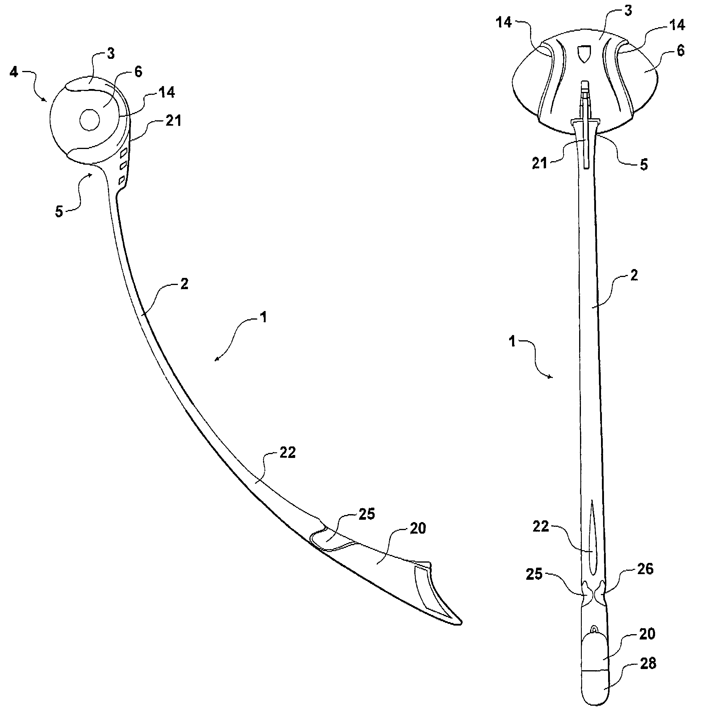
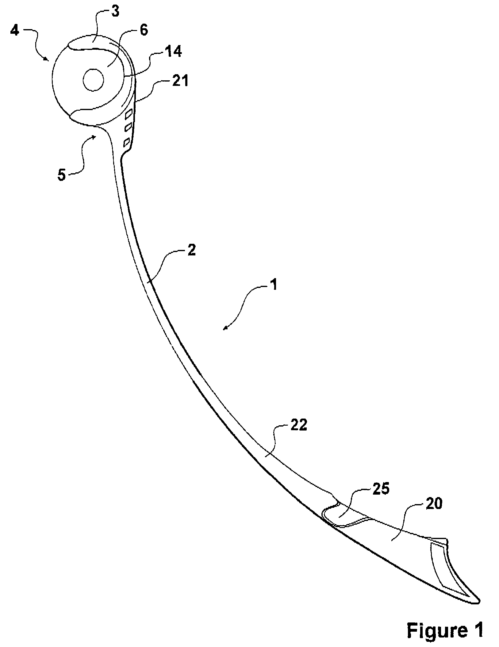
[0019]Referring to the drawings a throwing apparatus 1 is provided, which has an elongated handle 2 with a cup 3 mounted thereon.

[0020]The elongated handle 2 may be formed of a somewhat stiff plastics material but preferably having some flexibility and be curved along its length.

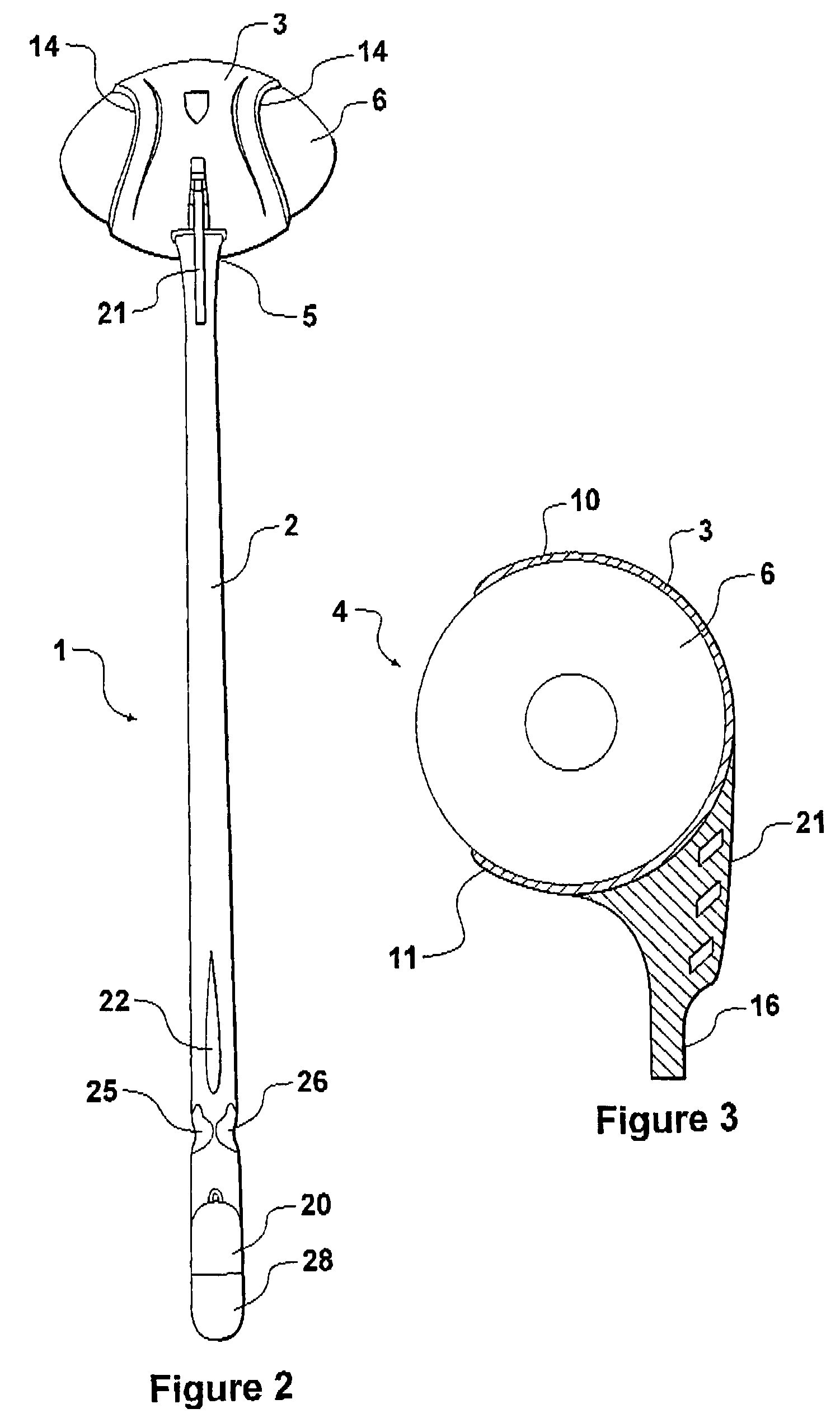
[0021]The length could be any desirable length for example approximately half a meter. The curve can be effected at a consistent rate or can be formed in an other shape as is desired. The purpose of the shape is essentially to enable the device to be held with the handle somewhat upright in a hand of the user whilst at that point the mouth 4 of the cup points substantially directly ahead. To this end the angle at the point of the attachment 5 of the handle 2 to the cup 3 is desirably so that the longitudinal axis of the handle at that point forms substantially a right angle with the direction that the object which will be held in the cup 3 will exit the cup in use.

[0022]The cup 3 has, in the preferred form, ...


PUM


Abstract

The invention consists in a throwing apparatus comprising an elongated handle and a cup mounted on the handle at or adjacent one end thereof. The cup is shaped to receive a throwable, non spherical, object and to retain such object until the handle is swung whereupon the object is released from the cup.

Description

[0001]This invention relates to throwing apparatus and in particular manually operated throwing apparatus.[0002]Throughout the description and claims of this specification the word “comprise” and variations of that word, such as “comprises” and “comprising”, are not intended to exclude other additives, components, integers or steps.BACKGROUND OF THE INVENTION[0003]It is often desired for play, relaxation, pleasure or sporting competition to throw a throwable object significant distances. Where the object is not spherical the difficulty of throwing is increased as it is necessary to hold the throwable object in particular ways to achieve distance for example by making the throwable object spin in flight.[0004]Accordingly, there is a need for a means which will enable non spherical objects such as some balls to be thrown a maximum distance.SUMMARY OF THE INVENTION[0005]It is therefore an object of the person invention to provide a throwing apparatus and / or a method of throwing which w...

Claims


Application Information

Patent Timeline
Patent Type & Authority Patents(United States)
IPC IPC(8): F41B3/00
CPCA63B59/02A63B43/002A63B59/0025A63B59/20A63B60/08A63B60/10A63B60/12
Inventor FITT, CARL DOUGLAS
Owner FITT CARL DOUGLAS
Why Eureka
Try Eureka