Bicycle helmet with reinforcement structure

a technology of bicycle helmets and reinforcement structures, applied in the field of protective helmets and bicycle helmets, can solve the problems of increasing the overall weight of the helmet, increasing the thickness of the helmet, and being more bulky

Active Publication Date: 2010-04-20
SPECIALIZED BICYCLE COMPONENTS INC
View PDF57 Cites 13 Cited by
  • Summary
  • Abstract
  • Description
  • Claims
  • Application Information

AI Technical Summary

Problems solved by technology

However, both these approaches tend to increase the overall weight of the helmet.
Additionally, increasing the addition of a shell increases the thickness of the helmet, making it more bulky.

Method used


Image

  • Bicycle helmet with reinforcement structure
  • Bicycle helmet with reinforcement structure
  • Bicycle helmet with reinforcement structure

Examples


Embodiment Construction

[0029]In the following detailed description, terms of orientation such as “top,”“bottom,”“upper,”“lower,”“front,”“rear,”“left,”“right” and “center” are used herein to simplify the description of the context of the illustrated embodiments. Likewise, terms of sequence, such as “first” and “second,” are used to simplify the description of the illustrated embodiments. Because other orientations and sequences are possible, however, the present invention should not be limited to the illustrated orientation. Those skilled in the art will appreciate that other orientations of the various components described above are possible. As used herein, “front”, “rear”, “left” and “right” are interpreted from the point of view of a user of a protective helmet. Likewise, “top”, “bottom”, “upper” and “lower” are interpreted from the point of view of the wearer of the helmet.

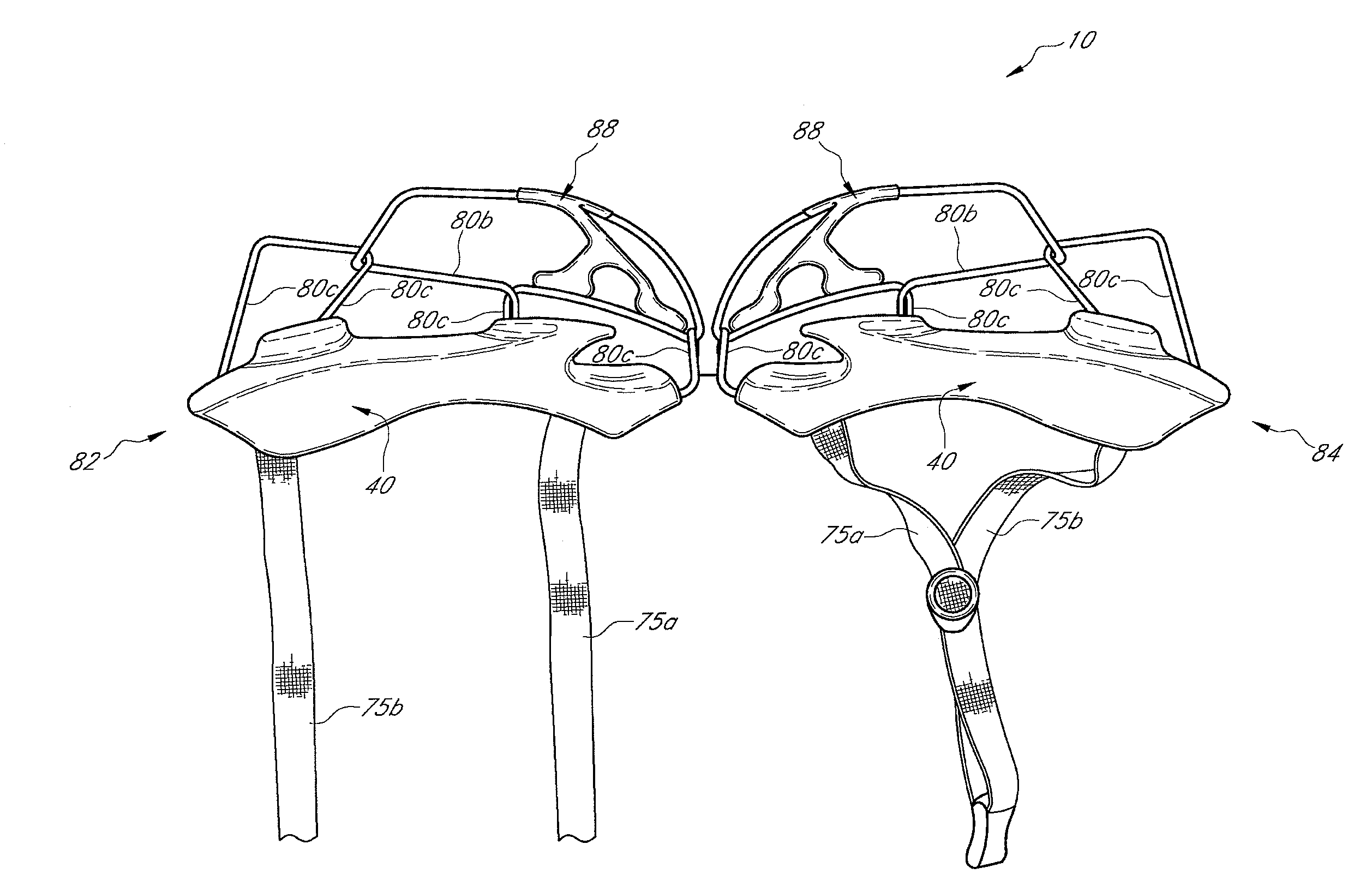
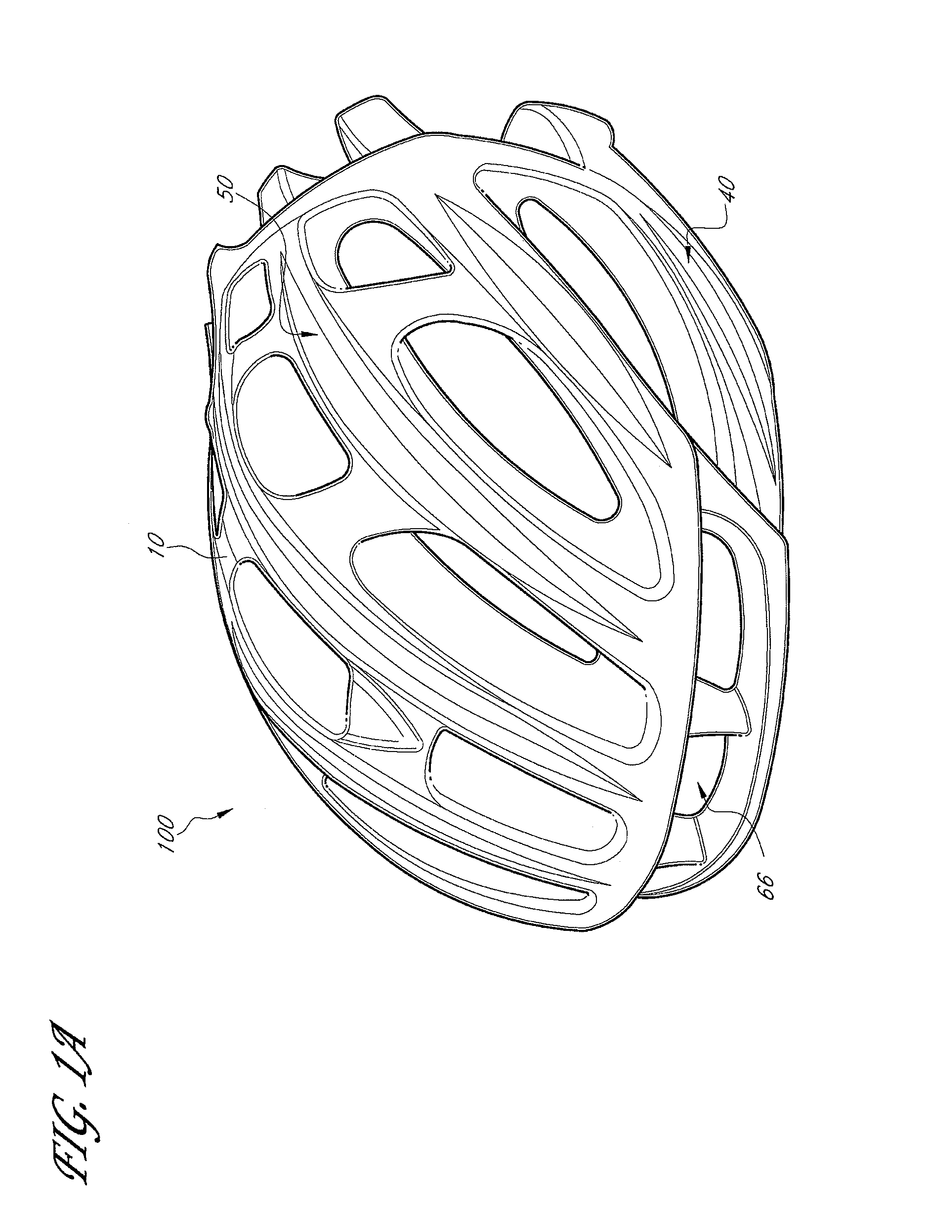
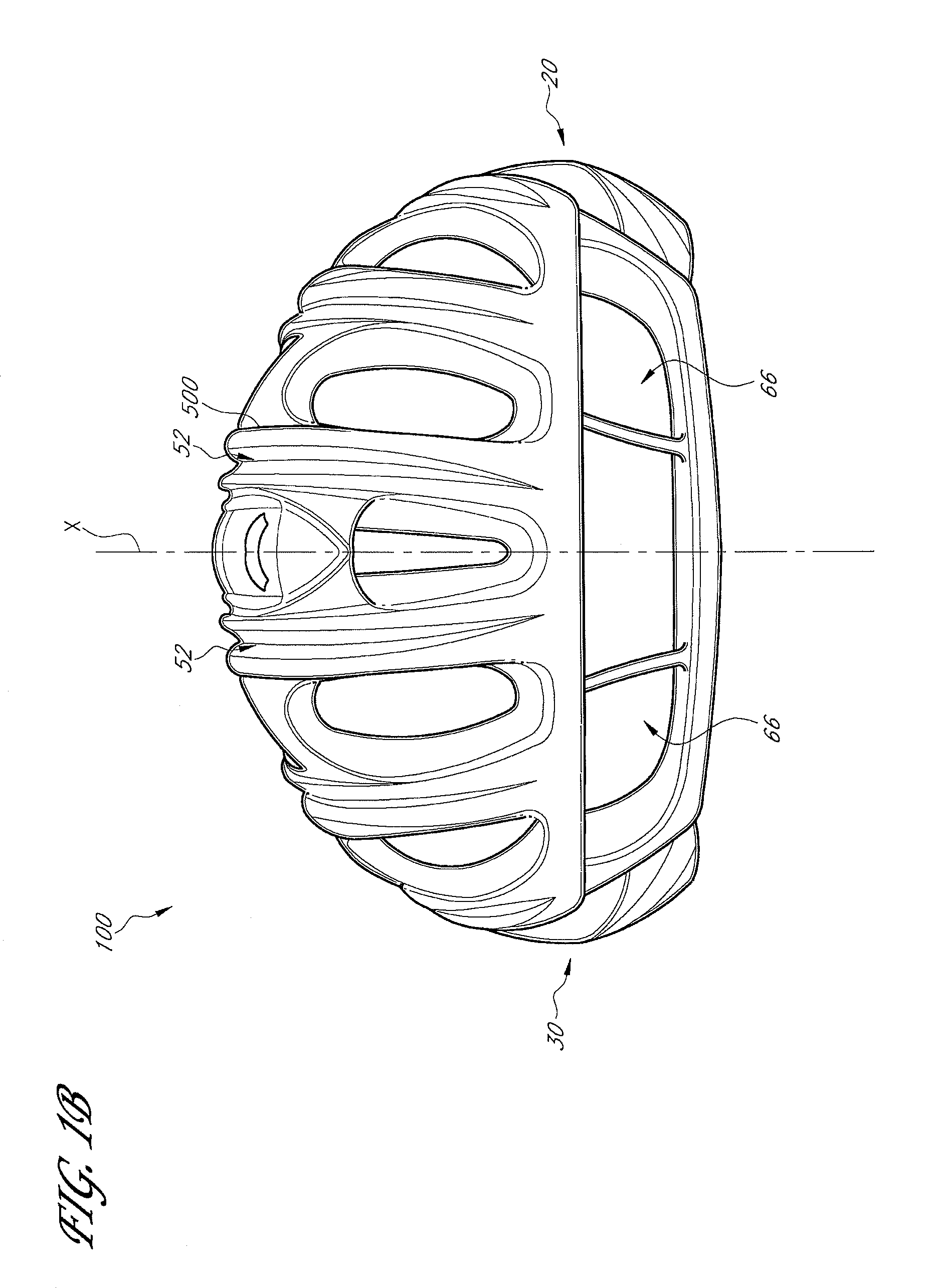
[0030]FIGS. 1A-1E illustrate one preferred embodiment of a protective helmet, which is especially well suited for use as a bicycle...


PUM


Abstract

A bicycle helmet has a body with a concave inner surface configured to permit the helmet to fit a user's head. The helmet also includes a reinforcement structure having a plurality of separate frames interconnected with each other, at least one of the plurality of frames comprising a unidirectional filament, wherein the reinforcement structure engages the body.

Description

CROSS-REFERENCE TO RELATED APPLICATIONS[0001]This application claims the benefit of U.S. Provisional Application No. 60 / 801,639, filed May 19, 2006, titled BICYCLE HELMET WITH REINFORCEMENT STRUCUTRE, and the benefit of U.S. Provisional Application No. 60 / 801,668, filed May 19, 2006, titled BICYCLE HELMET WITH REINFORCEMENT STRUCUTRE, the entire contents of both of which are incorporated by reference and should be considered a part of this specification.BACKGROUND OF THE INVENTION[0002]1. Field of the Invention[0003]The present invention relates to protective helmets and bicycle helmets in particular. More specifically, the present invention relates to a helmet with a unidirectional filament internal reinforcement structure.[0004]2. Description of the Related Art[0005]Conventional bicycle helmets typically employ a layer of crushable material, usually synthetic resin foam, extending over and about the wearer's head to mitigate the force of an impact, for example, due to a fall. Conv...

Claims


Application Information

Patent Timeline
Patent Type & Authority Patents(United States)
IPC IPC(8): A42B3/00
CPCA42B3/066
Inventor BULLOCK, CHRISTOPHER
Owner SPECIALIZED BICYCLE COMPONENTS INC
Why Eureka
Try Eureka