
Bicycle helmet with reinforcement structure

A technology for strengthening structures and bicycles, which is applied to helmets, helmet covers, household appliances, etc., and can solve the problems of increasing the overall weight of the helmet, making the helmet larger, and increasing the layer of crushable materials.

Active Publication Date: 2007-11-21
SPECIALIZED BICYCLE COMPONENTS INC
View PDF0 Cites 7 Cited by
  • Summary
  • Abstract
  • Description
  • Claims
  • Application Information

AI Technical Summary

Problems solved by technology

However, these methods increase the overall weight of the helmet
Also, incre

Method used


Image

  • Bicycle helmet with reinforcement structure
  • Bicycle helmet with reinforcement structure
  • Bicycle helmet with reinforcement structure

Examples


Embodiment Construction

[0036] In the detailed description that follows, orientation terms such as "top", "bottom", "upper", "lower", "front", "rear", "left", "right" and "center" will be used for The description of the contents of the illustrated embodiment is simplified. Also, ordinal terms such as "first" and "second" will be used to simplify the description of the illustrated embodiments. However, the invention should not be limited to the orientation shown, as other positions and orders are possible. Those skilled in the art will appreciate that other locations for the various components described above are possible. As used herein, "front", "rear", "left" and "right" are illustrated from the perspective of a user of the protective helmet. Likewise, "top", "bottom", "upper" and "lower" are illustrated from the perspective of the helmet wearer.

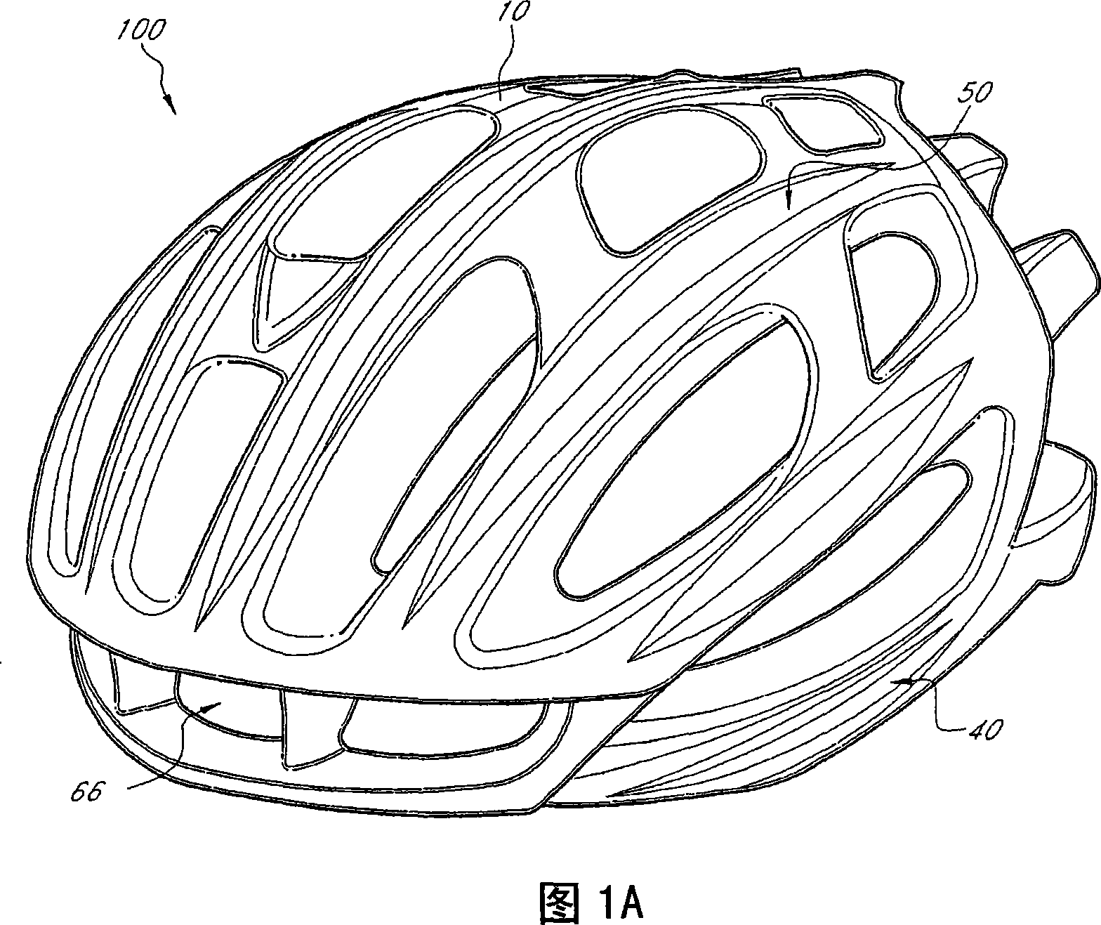
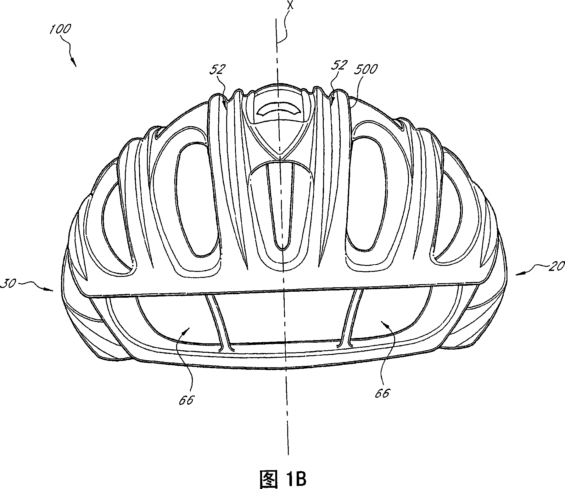
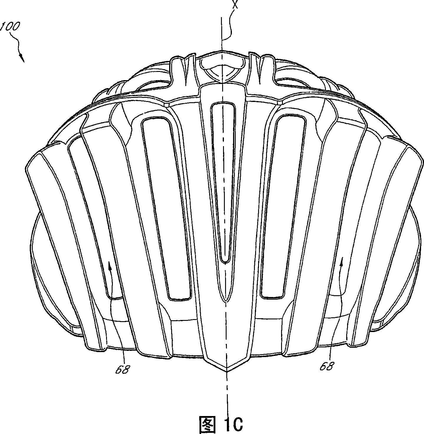
[0037] 1A-1E illustrate a preferred embodiment of a protective helmet particularly suitable for use as a bicycle helmet 100 . The helmet 100 include...


PUM


Abstract

A bicycle helmet has a body with a concave inner surface configureured to permit the helmet to fit a user's head. The body has a first section with a first density and a second section with a second density different from the first density. A reinforcement structure is disposed in the body, wherein the reinforcement structure engages the first and second portions of the body.

Description

[0001] Cross-references to related applications [0002] This application claims U.S. Provisional Patent Application No. 60 / 801,639, filed May 19, 2006, U.S. Provisional Patent Application No. 60 / 801,668, filed May 19, 2006, Priority of U.S. Patent Application No. 11 / 425,331, filed June 20, 2006, and U.S. Patent Application No. 11 / 425,350, filed June 20, 2006, all of which The content should be considered part of this article. technical field [0003] The present invention relates to a protective helmet, in particular, the present invention relates to a bicycle helmet. More specifically, the present invention relates to a helmet having multiple-density foam parts interconnected by a reinforcing structure. Background technique [0004] Conventional bicycle helmets typically utilize layers of crushable material, usually synthetic resin foam, spread around the wearer's head to mitigate impact forces such as those resulting from falls. To increase the impact strength of a hel...

Claims


Application Information

Patent Timeline
IPC IPC(8): A42B3/06
CPCA42B3/066B29C70/30A42C2/002A42B3/062B29L2031/4821B29C70/20
Inventor 克里斯托弗·布勒克
Owner SPECIALIZED BICYCLE COMPONENTS INC
Learn More