Aerodynamic bicycle helmet

a bicycle helmet and frontal viewing technology, applied in the direction of bicycle equipment, steering devices, instruments, etc., can solve the problems of increased coefficient of drag, bicycle helmets without air apertures, violent and uncontrolled fall of bicycle riders, etc., to reduce aerodynamic drag, lowered head position, and lowered head position

Inactive Publication Date: 2011-10-27
FELT RACING
View PDF0 Cites 9 Cited by
  • Summary
  • Abstract
  • Description
  • Claims
  • Application Information

AI Technical Summary

Benefits of technology

[0032]In a second embodiment of the system, a handlebar mounted bicycle video system is provided. The bicycle handlebar mount is configured to attach to a bicycle handlebar. In this regard the mount may be a clamp or any similar device used to attach to the bicycle handlebar. The mount is configured to rigidly attach to the bicycle handlebar. A video camera is disposed within the bicycle handlebar mount. The video camera is positioned in a manner such that the video camera is directed toward an area in front of the bicycle handlebar. The video camera is configured to capture real time images similar to the image a bicyclist with an elevated head position may view. The handlebar mounted bicycle video system also includes a flexible shaft. The flexible shaft extends from the bicycle handlebar mount. The flexible shaft includes a proximal end and a distal end. The proximal end of the flexible shaft is coupled to the bicycle handlebar mount. A video display is also associated with the handlebar mounted bicycle video system. The video display is in electrical communication with the video camera for receiving a signal representative of real time images of the area in front of the bicycle handlebar. The video display is coupled to the distal end of the flexible shaft. The configuration of the flexible shaft allows for the video display to b

Problems solved by technology

If a rim breaks, or cars and other cyclists crash into the bicycle rider, the bicycle rider may fall to the ground in a violent and uncontrolled motion.
Unfortunately, due to the discontinuities formed by the apertures in the helmet as well as the rider's facial features, there is an increased coefficient of drag.
The bicycle helmet does not incorporate apertures for providing air flow through the helmet to cool down the rider's head during a bike ride.
Unfortunately, the bicycle rider must still look upwards so that the rider's face is in the direction of wind flow.
Also, the rider's neck will be strained for having to look up all the time.
Unfortunately, this is not a comfortable position.
This up position creates neck strain thereby causing discomfort and potential long term physical problems to the rider.
The power generated by a bicyclist has its human limitations.
The main obstacle to aerodynamic efficiency at high speeds is wind resistance.
Most recreational bicycles in which the bicyclist is seated in an upright riding position have very poor aerodynamics.
While new bicycles are being designed with better aerodynamics in mind, the human body is simply not we

Method used


Image

  • Aerodynamic bicycle helmet
  • Aerodynamic bicycle helmet
  • Aerodynamic bicycle helmet

Examples


first embodiment

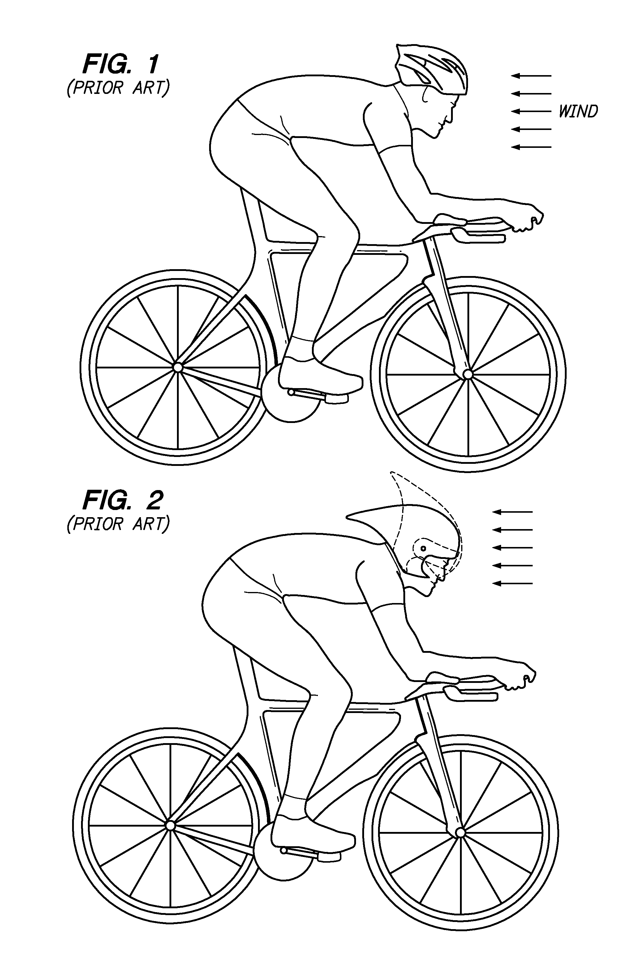
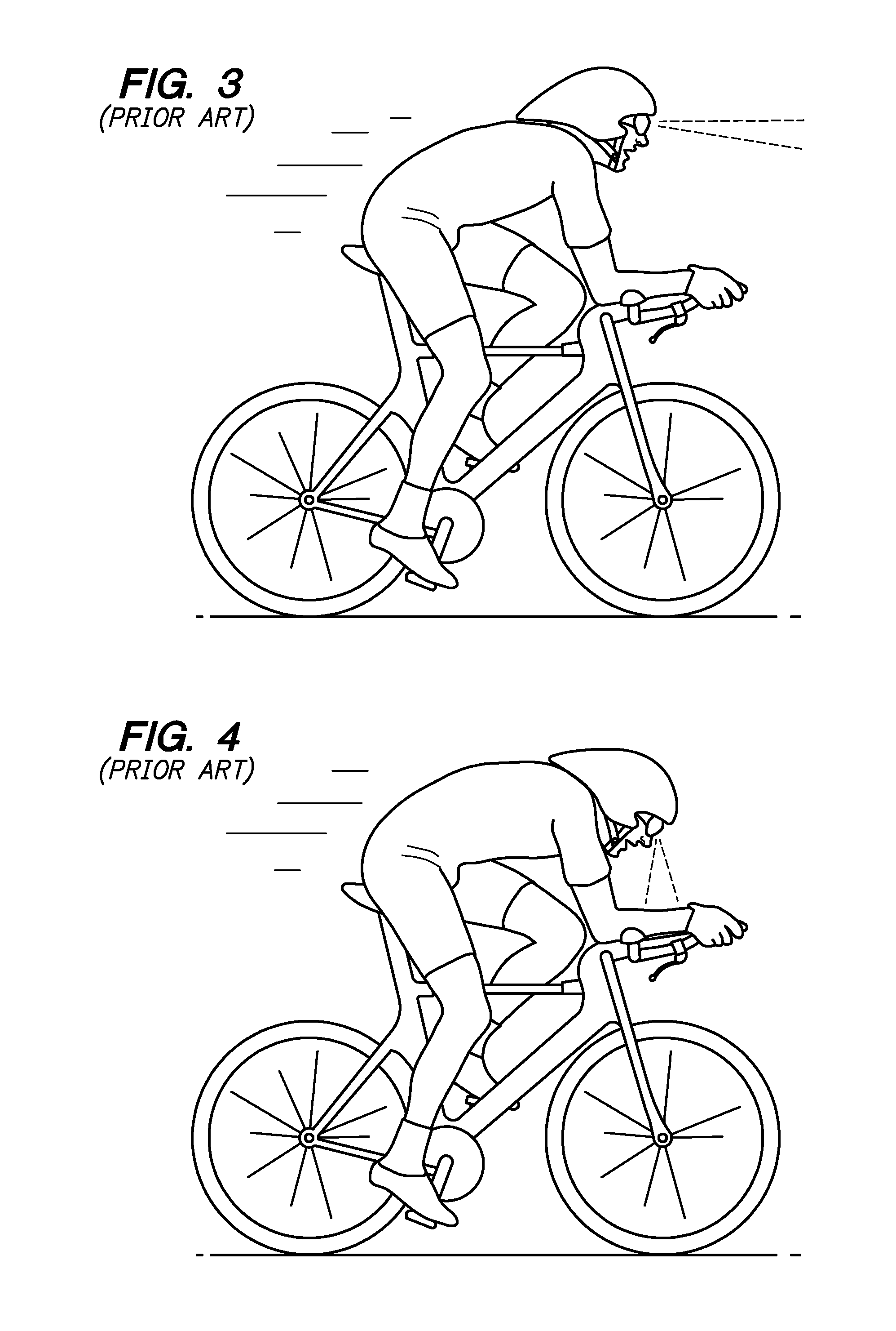
[0067]Referring now to FIGS. 5 and 6, the helmet 10 is shown. The helmet 10 incorporates a parabolic leading portion 26. When the rider is riding the bicycle 24 and the rider's head is in the downward position, the parabolic leading portion 26 initially contacts the oncoming wind 15 and splits the wind flow around the helmet 10 as shown by arrows 28a, b above and below the helmet 10. When the rider's head is in the downward position, as shown in FIG. 5, the upper and lower profiles 30a, b of the helmet 10 are generally symmetrical about axis 32 which may be generally parallel to a forward direction 34 of the bicycle 24. Also, a tail portion 36 of the upper profile 30a may generally blend with a back surface 38 of the rider 40. A low pressure is not created behind the rider's helmet 10 when the rider's head is in the downward position. The air 15 flows over the upper profile 30a and the back surface 38 of the rider 40. The rider does not have to lift up his / her head to look forward s...

second embodiment

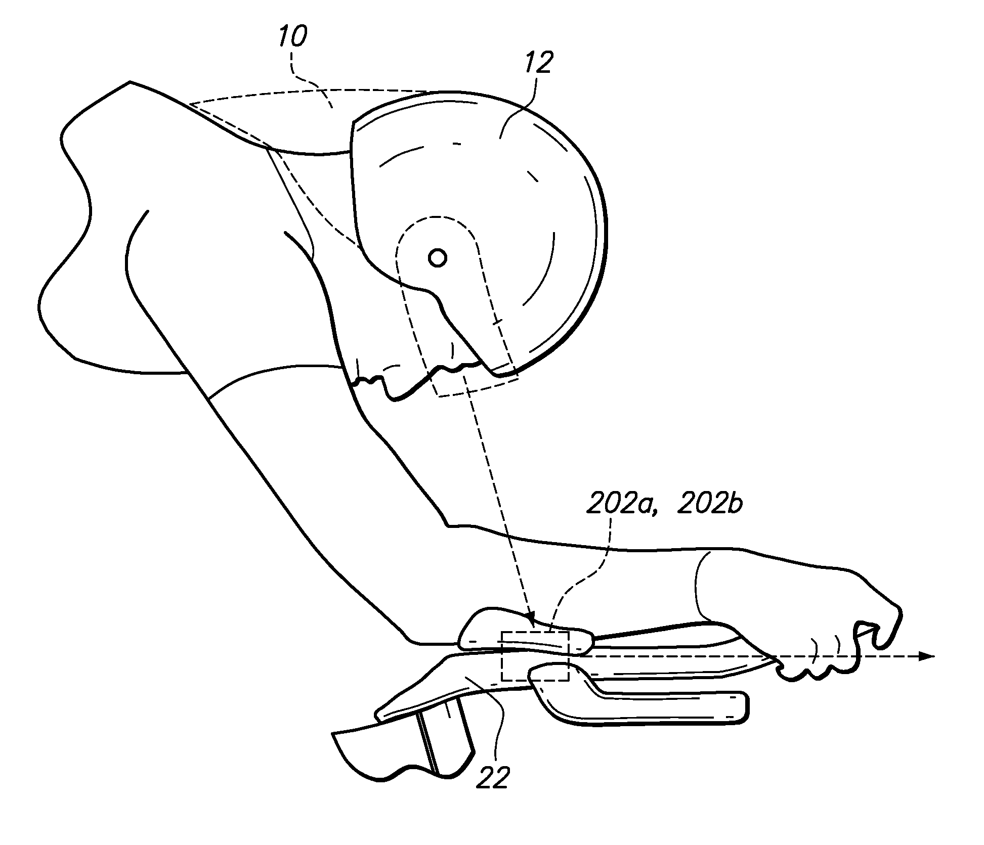
[0071]Referring now to FIGS. 7 and 8, the helmet 12 is shown. Instead of a parabolic leading portion, the leading portion 44 has a spherical configuration. The wind 15 contacts the leading portion 44 and is split up by the spherical leading portion 44. When the rider 50 is in the aggressive position shown in FIG. 7, and the rider's head is looking downward, the oncoming wind 15 initially contacts the spherical leading portion 44. The oncoming wind 15 is diverted above and below the helmet 12 as shown by directional arrow 46a, b. The helmet 12 does not have a rear tail portion 36 that blends with the rider's back surface 38. Rather, the trailing surface 57 follows the contour of the rider's head. This minimizes any low pressure behind the helmet 12 caused by the oncoming wind 15. The oncoming wind 15 flowing in the direction of arrow 46a traverses over the helmet 12 and over the back surface 38 of the rider 50. The oncoming wind 15 also flows under the helmet 12 and under the face ma...


PUM


Abstract

A minor based front viewing system is disclosed. The front viewing system may be worn by the rider similar to an eyeglass or mounted to a handlebar region of the bicycle. The rider can also wear an aerodynamic helmet and use the front viewing system or video display system in conjunction with the aerodynamic helmet so that the rider can maintain his/her head in a down position to take advantage of the aerodynamic characteristics of the aerodynamic helmet.

Description

CROSS-REFERENCE TO RELATED APPLICATIONS[0001]This application is a continuation in part application of U.S. patent application Ser. No. 12 / 766,212, filed on Apr. 23, 2010, the entire content of which is expressly incorporated herein by reference.[0002]This application is also related to U.S. patent application Ser. No. 12 / 257,124, filed on Oct. 23, 2008, the entire content of which is expressly incorporated herein by reference.STATEMENT RE: FEDERALLY SPONSORED RESEARCH / DEVELOPMENT[0003]Not ApplicableBACKGROUND[0004]The present invention relates to a helmet for a bicycle and a frontal viewing system configured to facilitate reduction of aerodynamic drag associated with a riding position on a bicycle.[0005]Helmets are worn by bicycle riders to protect the rider's head in the event of a crash. The helmet absorbs the shock of the crash instead of the rider's head. Road bicycles at competition levels exceed speeds of 25 miles per hour. If a rim breaks, or cars and other cyclists crash in...

Claims


Application Information

Patent Timeline
IPC IPC(8): B62J29/00G02B5/10A42B1/24
CPCA42B3/0426A42B3/0493B62J99/00G02C5/003B62J2099/0033B62J2099/008B62K21/125B62J2099/0026B62J50/20B62J50/225
Inventor FELT, JAMES MICHAEL
Owner FELT RACING
Why Eureka
Try Eureka