Locking device

a technology of locking device and latching lock, which is applied in the direction of latching lock, cylinder lock, hollow article cleaning, etc., can solve the problem of limit in ensuring safety

Inactive Publication Date: 2010-04-20
KIM GAB SIK
View PDF26 Cites 21 Cited by
  • Summary
  • Abstract
  • Description
  • Claims
  • Application Information

AI Technical Summary

Benefits of technology

[0016]In the locking device according to the present invention, a cylinder cannot be rotated and a locking plate cannot be operated by an illegal method. Also, even though the cylinder is destroyed, the locking plate cannot be operated.

Problems solved by technology

However, such a structure that the locking plate is mechanically connected with the cylinder device has limitation in ensuring safety essential to the locking device.
Most of the locking devices are designed in such a manner that a key having no approval cannot be inserted into a cylinder device or the cylinder device cannot be rotated even if such a key is inserted into the cylinder device.
Therefore, people who illegally try to open the locking device are likely to insert the key or another similar tool into the cylinder device to rotate the cylinder device.
In another case, people may drive the locking plate by destroying the cylinder device.

Method used


Image

  • Locking device
  • Locking device
  • Locking device

Examples


Embodiment Construction

[0023]Hereinafter, a locking device according to the present invention will be described in detail with reference to the accompanying drawings.

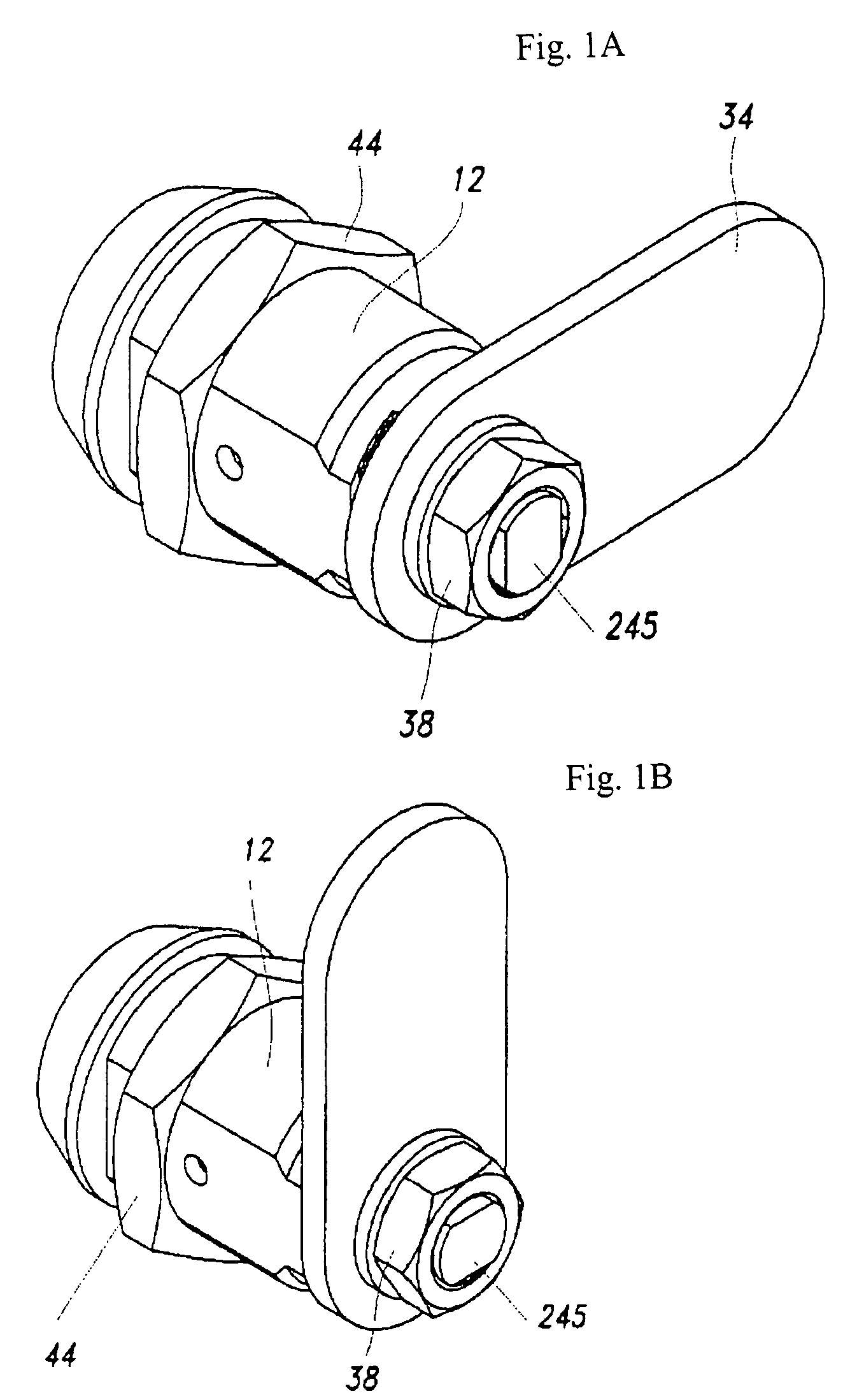
[0024]FIG. 1 illustrates a locking device according to the present invention, in which FIG. 1A illustrates the state that a locking device 1 is locked and FIG. 1B illustrates the state that the locking device 1 is opened.

[0025]If a key is inserted into a cylinder device in a state that the locking device 1 according to the present invention is locked as shown in FIG. 1A, a motor constituting the cylinder device located in a housing 12 is driven so that the cylinder device can be rotated. In this state, if the key is turned, the cylinder device inside the housing 12 is rotated so that a locking plate 34 connected with a rotary shaft 245 of the cylinder device is rotated to open the locking device. A reference numeral 44 represents a nut for installing the locking device in a drawer of a desk or a door of a closet.

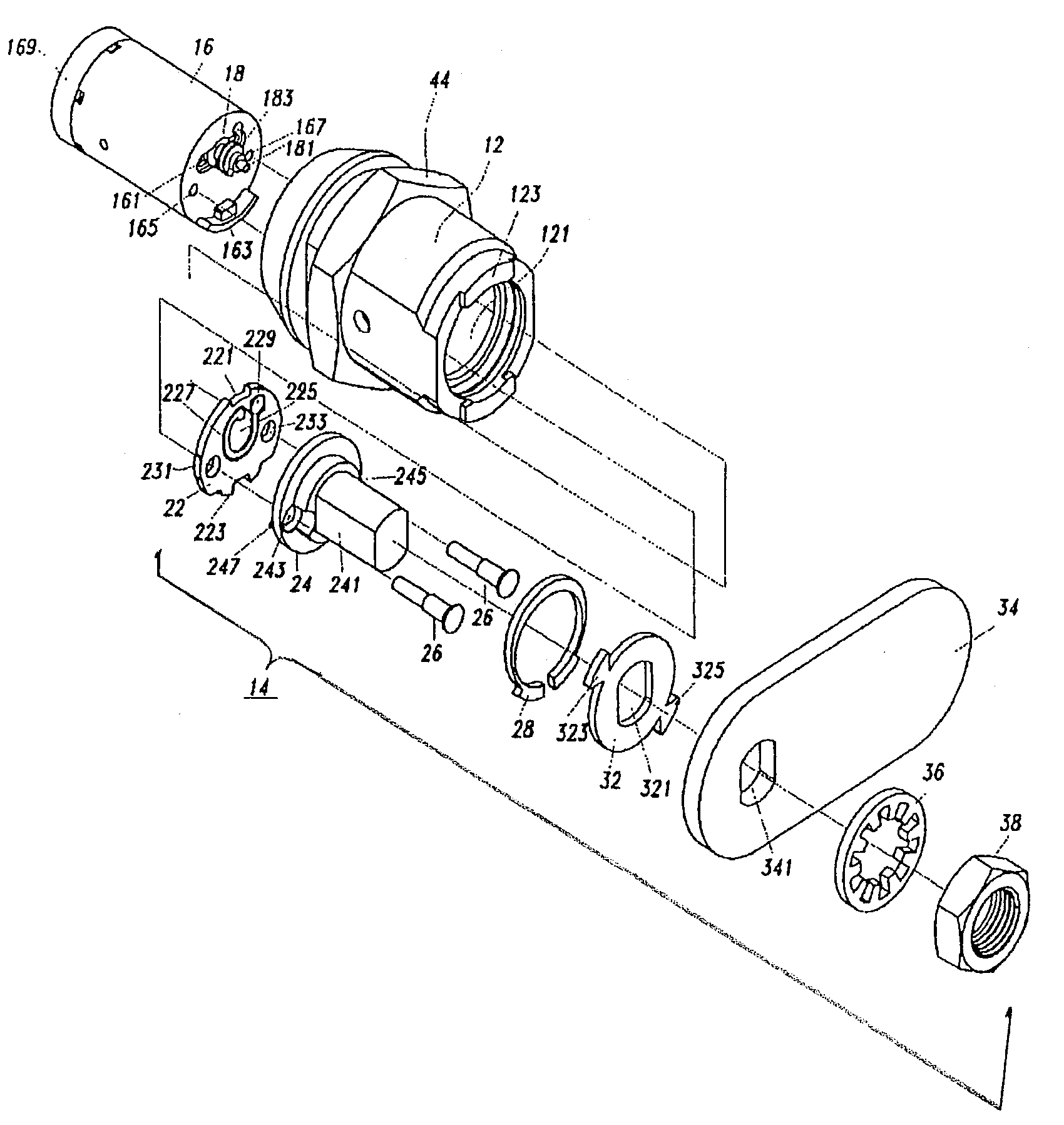
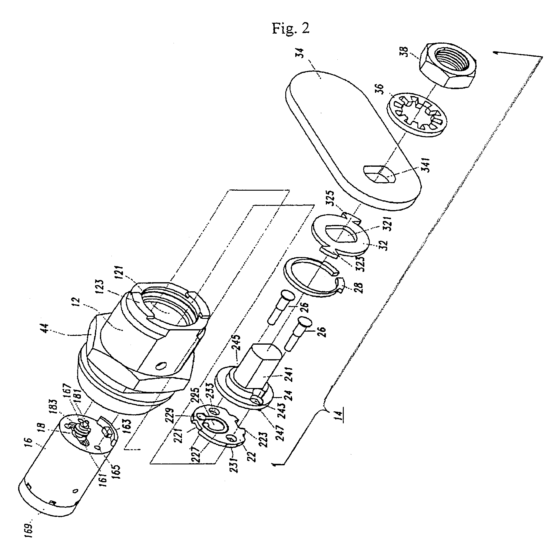
[0026]FIG. 2 is an exploded pe...


PUM


Abstract

Disclosed is a locking device which comprises a housing, and a cylinder device rotating within the housing, wherein the housing is provided with a protrusion therein to prevent the cylinder device from being rotated, and the cylinder device includes a motor, a cylinder receiving the motor, a tilting mechanism located at the front of the cylinder, having an upper portion tilted to be fixed to the protrusion of the housing by forward rotation of the motor and a recess released from the protrusion of the housing by reverse rotation of the motor, and a locking plate adapter fixed to the tilting mechanism, and a locking plate fixed to the adapter.

Description

TECHNICAL FIELD[0001]The present invention relates to a locking device, and more particularly, to a locking device in which rotational driving of a cylinder device is controlled by a motor.BACKGROUND ART[0002]A locking device is designed in such a manner that a locking plate connected with a cylinder device is rotatably opened and closed after a key is inserted into the cylinder device to rotate the cylinder device.[0003]A locking plate of a general locking device is mechanically connected with a cylinder device.[0004]However, such a structure that the locking plate is mechanically connected with the cylinder device has limitation in ensuring safety essential to the locking device. Most of the locking devices are designed in such a manner that a key having no approval cannot be inserted into a cylinder device or the cylinder device cannot be rotated even if such a key is inserted into the cylinder device. However, if the cylinder device is once rotated, the locking plate is driven t...

Claims


Application Information

Patent Timeline
Patent Type & Authority Patents(United States)
IPC IPC(8): E05B47/00
CPCE05B47/0012E05B47/0642E05C3/042E05B2047/0016E05B2047/0026Y10T70/7062Y10T70/7113Y10T70/713Y10T70/5416Y10T70/7559B08B9/04B08B2209/04
Inventor KIM, GAB-SIK
Owner KIM GAB SIK
Why Eureka
Try Eureka