Orthodontic bracket

a technology for orthodontic brackets and brackets, applied in the field of orthodontic brackets, can solve the problems of increasing the difficulty of fabricating and assembling orthodontic brackets of this type, detracting from their usefulness, and increasing the dimensional size of the resulting bracket, so as to facilitate passive self-ligation

Active Publication Date: 2010-04-27
ORMCO CORP
View PDF7 Cites 85 Cited by
  • Summary
  • Abstract
  • Description
  • Claims
  • Application Information

AI Technical Summary

Benefits of technology

[0021]A further aspect of the present invention relates to an orthodontic bracket which includes a base member having an anterior and posterior facing surfaces, and which further defines a transverse archwire slot having an opening; a ligating slide which is moveably borne by the base member between a first position, where the ligating slide is clear of the archwire slot, and a second position, where the ligating slide projects over the opening of the archwire slot, and wherein the ligating slide moves along a path of travel between the first and second positions; a resilient member borne by the base member and cooperating with the ligating slide to releasably restrain the ligating slide in the first and second positions, and wherein the resilient member is resiliently deformed, and moves along an arcuately shaped path of travel when the ligating slide moves between the first and second positions; a transverse passageway formed in the base member and disposed in spaced relation relative to the archwire slot; and an orthodontic appliance received, at least in part, in the transverse passageway and which facilitates passive self-ligation.

Problems solved by technology

While the brackets of the prior art have worked with varying degrees of success, assorted shortcomings have detracted from their usefulness.
In particular, one of the chief difficulties with brackets having the designs as discussed, above, relates to the accurate manufacturing of same.
As will be clear from reviewing the several earlier mentioned prior art references, the positioning of a biasing member within the bracket body in order to biasingly cooperate with the ligating gate has typically increased the dimensional size of the resulting bracket, and further increased the difficulty associated with fabricating and assembling orthodontic brackets of this type.
For example, in brackets of this prior art design, if an archwire is not fully seated in the archwire slot, it becomes difficult if not impossible to fully engage the ligating slide with the bracket body thereby securing the ligating slide in the closed position over the archwire.
More specifically, in a design such as seen in the Carriere SLB, and wherein the cantilevered ligating slide must releasably engage the base member in order to remain closed over the archwire slot, it will be readily apparent that an unseated archwire may deflect or deform the ligating slide sufficiently so that it may not effectively engage the base member, and therefore remain closed over the archwire.
This is obviously a time consuming process for both the clinician as well as the patient.

Method used


Image

  • Orthodontic bracket
  • Orthodontic bracket
  • Orthodontic bracket

Examples


first embodiment

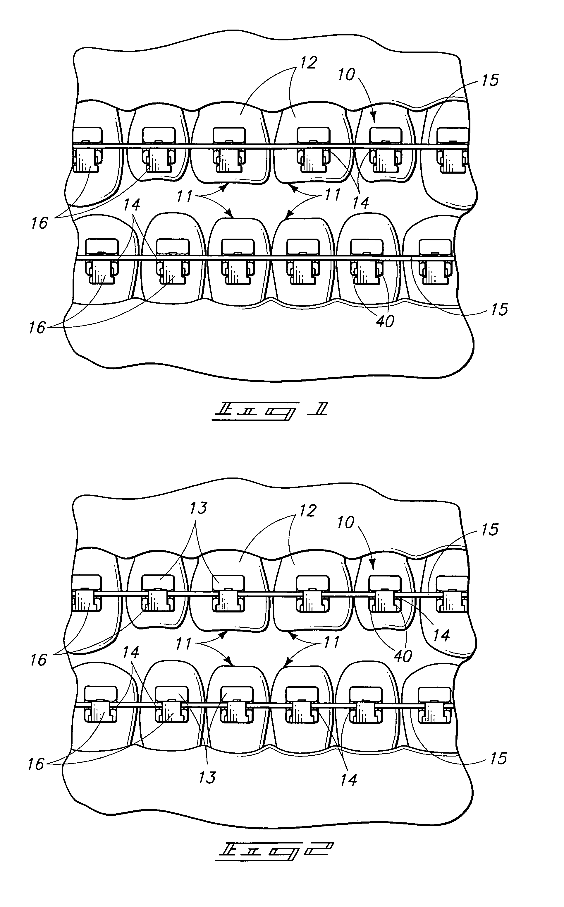
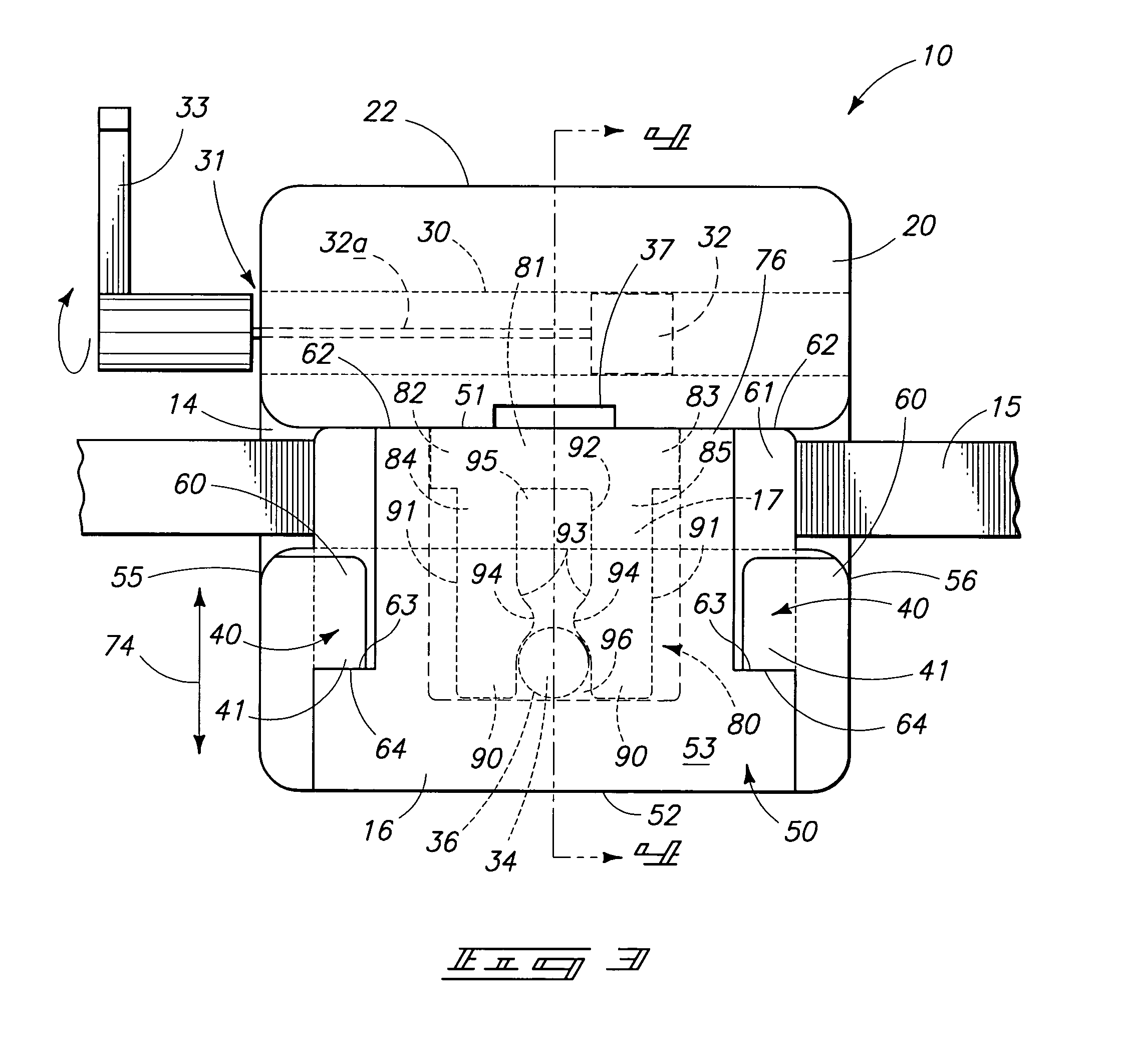
[0055]Five forms of a self-ligating orthodontic bracket are illustrated in the drawings. A first embodiment is shown in FIG. 1-10; a second form is illustrated in FIGS. 11-17; a third form is shown at FIG. 18; a fourth form is shown in FIGS. 21-25; and a fifth form is shown in FIGS. 26 and 27, respectively. Other inventive aspects of the present invention such as a novel orthodontic appliance to be employed in the various forms of invention (FIG. 19) are also shown in the various views, and will be discussed in greater detail in the paragraphs hereinafter.

[0056]The illustrated details of the orthodontic bracket of the present invention may be used in many different combinations within the scope of this disclosure. For this reason, the details of the illustrated orthodontic brackets, as described hereinafter, are intended to be interpreted as merely illustrative, and should not be taken as restrictive of the practical combinations of such features within the scope of this disclosure ...

second embodiment

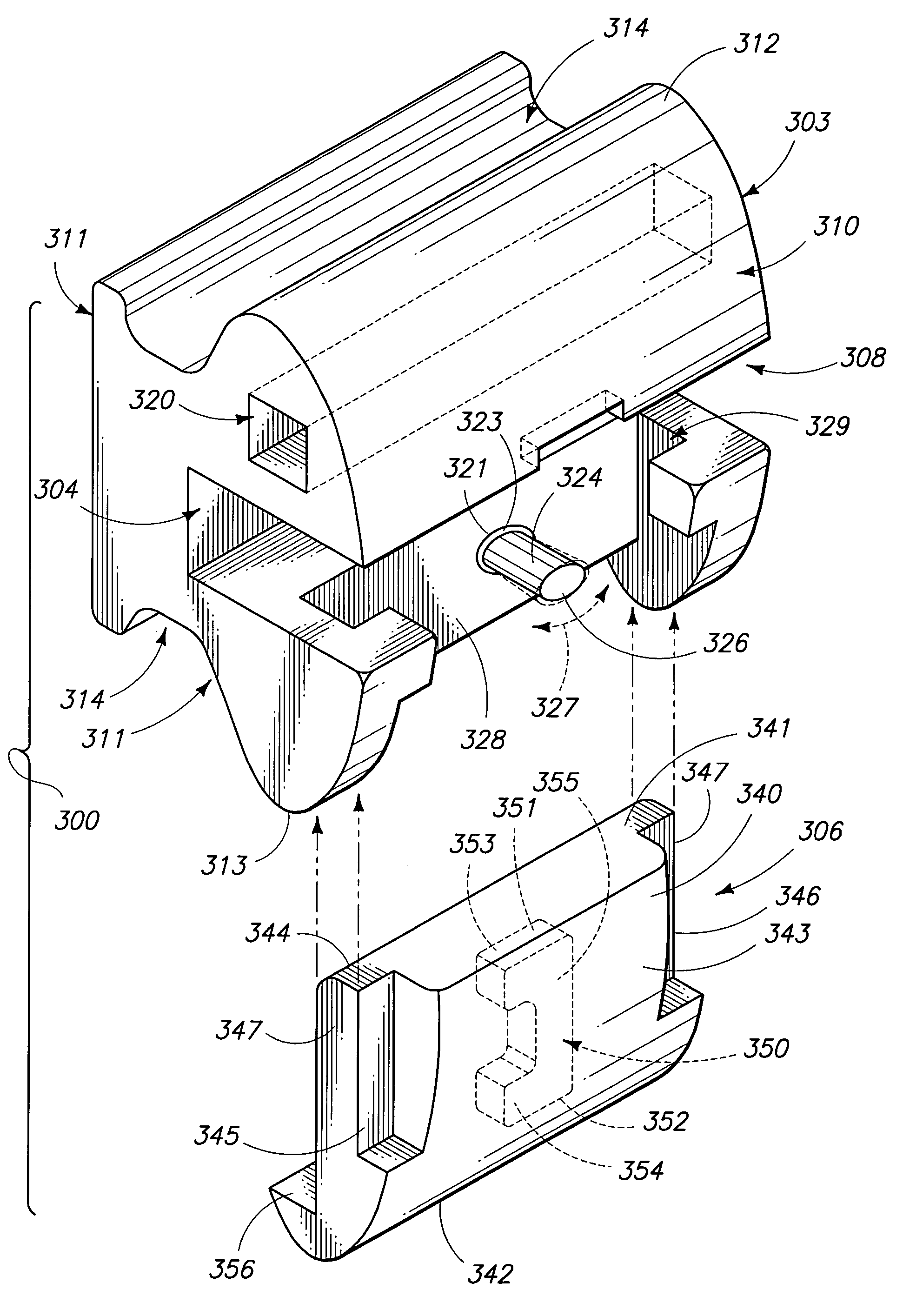
[0069]The second embodiment of the orthodontic bracket of the present invention is generally indicated by the numeral 100 and is best seen by reference to FIGS. 11-17A, respectively. As seen therein, the second embodiment of the orthodontic bracket 100 is defined by a bracket body or base member 103 and which further defines a transversely disposed archwire slot 104 which is operable to receive an archwire 105 of traditional design. As earlier discussed, the archwire slot is shown in a transverse orientation relative to the bracket body or base member 103, however, it will be appreciated that the archwire slot 104 may be oriented in various orientations to achieve various clinical benefits for a patient. As seen in the drawings, the archwire slot 104 is substantially rectangular in shape, and is operable to receive a rectangular shaped archwire 105 of conventional design. The orthodontic bracket 100 includes a ligating slide 106 which moveably cooperates with the base member 103, an...

third embodiment

[0073]The third embodiment of the orthodontic bracket of the present invention is generally indicated by the numeral 200, and is best seen by reference to FIG. 18. As seen therein, the third embodiment of the orthodontic bracket 200 is defined by a bracket body or base member 203 and which further defines a transversely disposed archwire slot 204 which is operable to receive an archwire 205 of traditional design. As earlier discussed with respect to the first and second forms of the invention, the archwire slot 204 is shown in a transverse orientation relative to the bracket body or base member 203, however, it will be appreciated that the archwire slot 204 may be located in various orientations to achieve assorted clinical benefits for a patient. As seen in FIG. 18, the archwire slot 204 is substantially rectangular and is operable to receive a rectangular shaped archwire 205 of conventional design. The orthodontic bracket 200 further includes a ligating slide 206 which moveably co...


PUM


Abstract

An orthodontic bracket is described and which includes a base member defining an archwire slot having an opening, and at least one projection extending outwardly from the base member; a ligating slide moveable between a first position which is clear of the archwire slot, and second position where the ligating slide projects over the opening of the archwire slot; and a biasing member borne by the ligating slide, and resiliently cooperating with the projection, and wherein the biasing member has a first portion which receives the projection when the ligating slide is in the first position, and a second portion which receives the projection when the ligating slide is in the second position.

Description

TECHNICAL FIELD[0001]This disclosure pertains to an orthodontic bracket, and more specifically to biased ligating slides which are employed with same.BACKGROUND OF THE INVENTION[0002]Orthodontic brackets which are attached to the teeth of a patient, are designed to engage an archwire that exerts force upon the teeth to move the teeth into various clinically appropriate orientations. Such brackets typically include an archwire slot for reception of the archwire. Those skilled in the art will recognize that an archwire slot can have any desired cross-sectional configuration, or size, to match the size and shape requirements of the archwire or wires that are being received within the same slot.[0003]Heretofore, many orthodontic brackets have been adhesively bonded to a tooth with the archwire slot being oriented in a substantially parallel orientation relative to the occlusal plane. However, those skilled in the art have long recognized that the archwire slot can also be angularly orie...

Claims


Application Information

Patent Timeline
Patent Type & Authority Patents(United States)
IPC IPC(8): A61C3/00
CPCA61C7/287
Inventor DAMON, DWIGHT H.
Owner ORMCO CORP
Why Eureka
Try Eureka