Prosthetic foot with variable medial/lateral stiffness

a technology of prosthetic feet and lateral joints, applied in the field of prosthetic feet with multi-axial rotation, can solve the problems of unnatural, unnatural, unbalanced feel for users, and limited material and imagination in the development of functional and natural artificial

Inactive Publication Date: 2010-06-01
FREEDOM INNOVATIONS INC
View PDF173 Cites 37 Cited by
  • Summary
  • Abstract
  • Description
  • Claims
  • Application Information

AI Technical Summary

Benefits of technology

[0009]It has been recognized that it would be advantageous to develop a prosthetic foot with a variable stiffness arch block for providing smooth and steady multi-axial rotation laterally across the forefoot and heel regions of the foot to allow the wearer to maneuver uneven terrain. Additionally, it has been recognized that it would be advantageous to develop a prosthetic foot with a variable stiffness arch block for providing smooth and steady multi-axial rotation to assist with a natural medial to lateral roll-over of the prosthetic foot in response to uneven terrain.
[0010]In one aspect, the present invention provides for a prosthetic foot including an elongated foot member, extending between a toe section positioned at a toe location of a natural foot and a heel section positioned at a heel location of a natural foot. The elongated foot member also extends through an elevated arch section positioned between the toe section and heel section at a approximate arch location of a natural foot. An arch block is disposed below the elongated foot member under the elevated arch section. The arch block is sized and shaped to substantially fill a space or volume under the arch section. The arch block has geometric and physical properties that facilitate medial to lateral rotation to the prosthetic foot.

Problems solved by technology

With respect to prosthetic feet, the development of a functional and natural artificial foot has been limited by material and imagination.
Few designs consider the lateral, or side to side rotation of the foot when the foot is used on varied or uneven terrain.
This design is problematic, however, because the split creates at least two forefoot regions that can bend independent from one another and can result in an unnatural, out of balance feel to the user.

Method used


Image

  • Prosthetic foot with variable medial/lateral stiffness
  • Prosthetic foot with variable medial/lateral stiffness
  • Prosthetic foot with variable medial/lateral stiffness

Examples


Embodiment Construction

[0022]Reference will now be made to the exemplary embodiments illustrated in the drawings, and specific language will be used herein to describe the same. It will nevertheless be understood that no limitation of the scope of the invention is thereby intended. Alterations and further modifications of the inventive features illustrated herein, and additional applications of the principles of the inventions as illustrated herein, which would occur to one skilled in the relevant art and having possession of this disclosure, are to be considered within the scope of the invention.

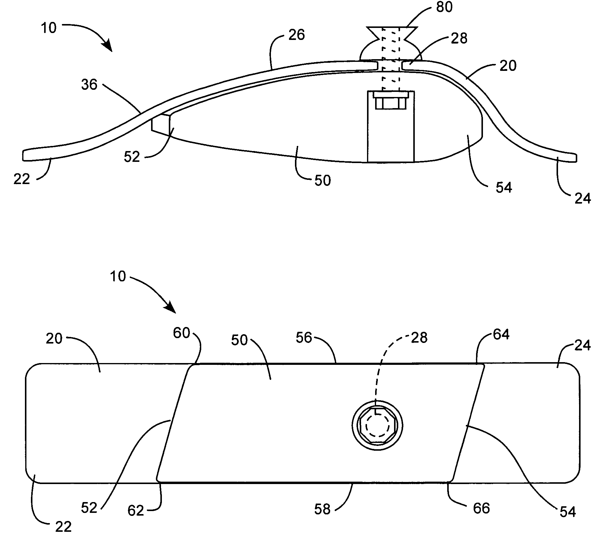
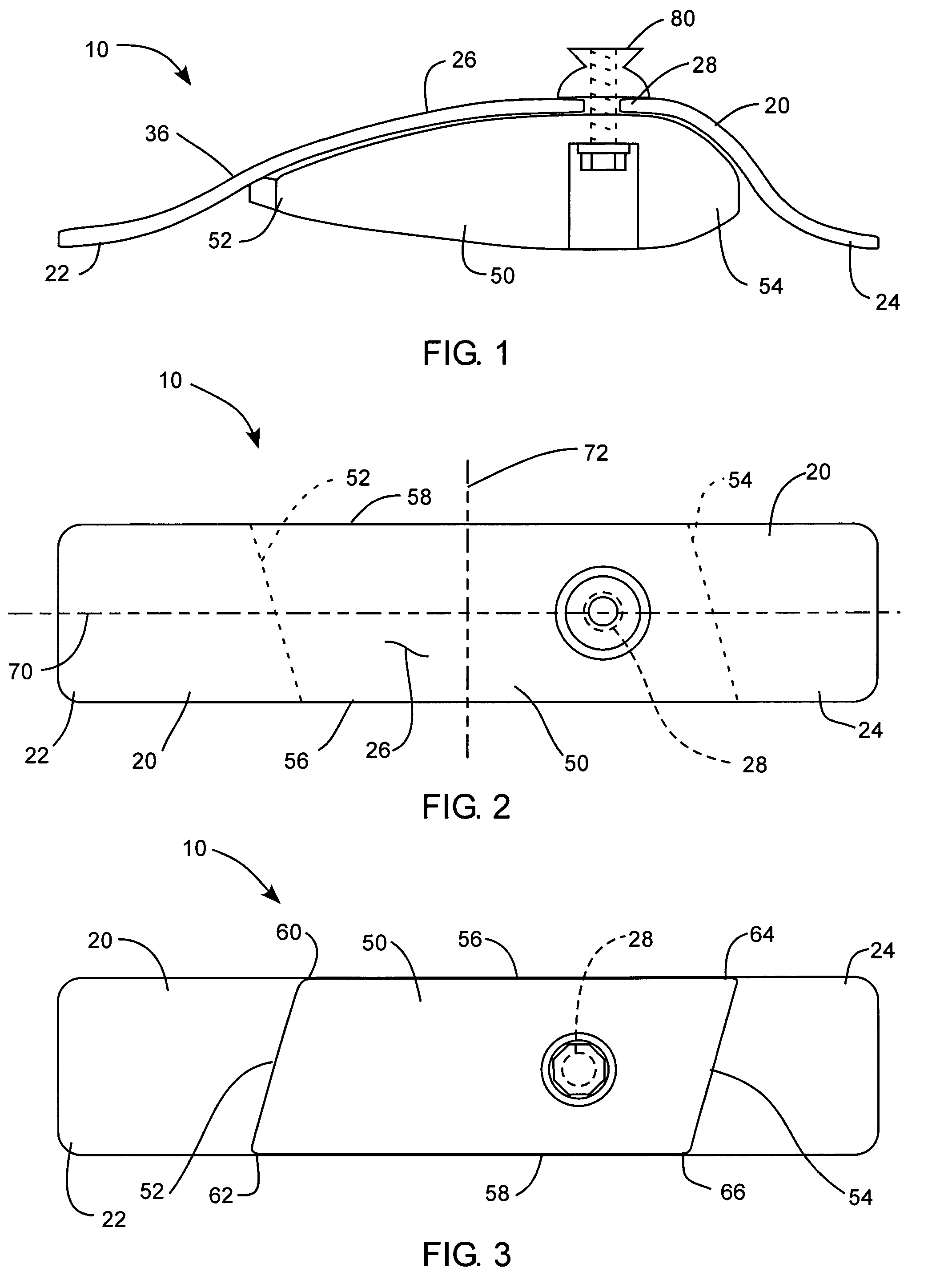
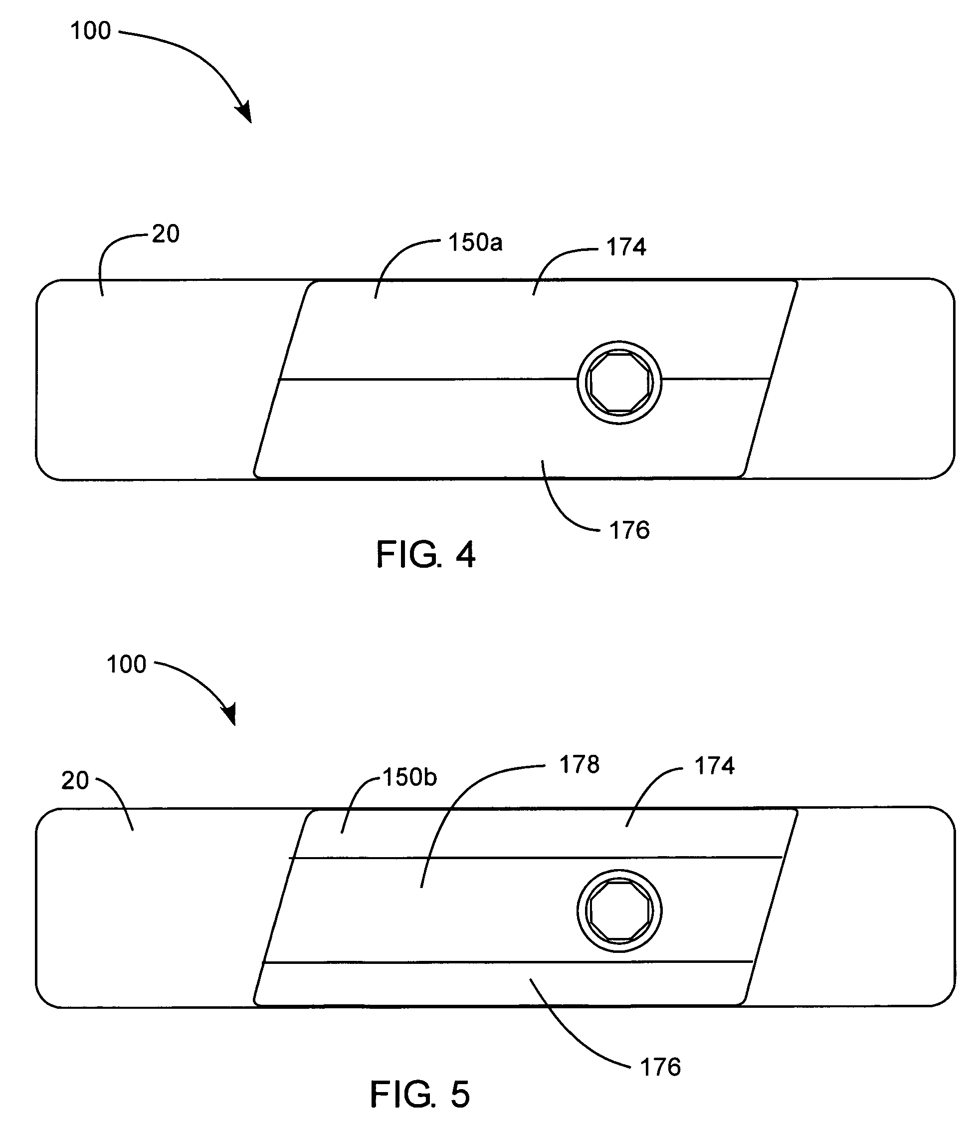
[0023]The present invention relates generally to a prosthetic foot with variable medial to lateral stiffness to provide for multiaxial medial to lateral rotation. The foot can have a resilient elongated foot member extending in an arcuate shape between a toe end and a heel end with an elevated attachment section between the toe end and the heel end. The attachment section can be elevated above the toe end and hee...


PUM


Abstract

A prosthetic foot includes an elongated foot member, extending between a toe section positioned at a toe location of a natural foot and a heel section positioned at a heel location of a natural foot. The elongated foot member also extends through an elevated arch section positioned between the toe section and heel section at an approximate arch location of a natural foot. An arch block is disposed below the elongated foot member under the elevated arch section. The arch block is sized and shaped to substantially fill a space or volume under the arch section. The arch block has geometric and physical properties that facilitate medial to lateral rotation to the prosthetic foot.

Description

PRIORITY CLAIM[0001]Benefit is claimed of U.S. Provisional Patent Application Ser. No. 60 / 898,106, filed Jan. 24, 2007, and U.S. Provisional Patent Application Ser. No. 60 / 901,854, filed Feb. 16, 2007 which are herein incorporated by reference in their entirety for all purposes.BACKGROUND OF THE INVENTION[0002]1. Field of the Invention[0003]The present invention relates generally to a prosthetic foot with multiaxial rotation.[0004]2. Related Art[0005]Many individuals have lost a limb for various reasons including war, accident, or disease. In most instances these individuals are not only able to live relatively normal lives, but physically active lives as well. Oftentimes, these individuals are aided in their everyday lives by a prosthetic limb. The objective of prosthesis is to provide an artificial limb that simulates the function and natural feel of the replaced limb.[0006]With respect to prosthetic feet, the development of a functional and natural artificial foot has been limite...

Claims


Application Information

Patent Timeline
Patent Type & Authority Patents(United States)
IPC IPC(8): A61F2/66
CPCA61F2/66A61F2002/30014A61F2002/30359A61F2002/30434A61F2002/5009A61F2250/0018A61F2002/6642A61F2002/6671A61F2220/0033A61F2220/0041A61F2002/6621A61F2002/30433
Inventor CHRISTENSEN, ROLAND J.BOREN, MARCUS
Owner FREEDOM INNOVATIONS INC
Why Eureka
Try Eureka