Apparatus and method for percutaneous catheter implantation and replacement

a technology of percutaneous catheter and implantation device, applied in the field of medical technology, can solve the problems of increasing the difficulty of removing and/or repositioning an implanted catheter, and causing the implanted catheter to become damaged, so as to avoid tissue damage to the patient, easy peeling of the sheath, and easy fracture

Active Publication Date: 2010-06-08
INCUMED LLC A NEVADA LIMITED LIABILITY +1
View PDF48 Cites 11 Cited by
  • Summary
  • Abstract
  • Description
  • Claims
  • Application Information

AI Technical Summary

Benefits of technology

[0005]The present invention is directed to a medical apparatus and method of use for percutaneously implanting an elongate conduit, e.g., a catheter or cable, in a patient's body in a manner which allows the conduit to be easily positioned, repositioned, and replaced.
[0006]An apparatus in accordance with the invention includes an elongate sleeve comprising a wall surrounding an interior elongate passageway. The passageway extends from a sleeve proximal end to a sleeve distal end. The sleeve is intended to be percutaneously implanted through an incision in the patient's skin so that the sleeve distal end resides beneath the skin, i.e., subcutaneously, and the sleeve proximal end resides above the skin. The sleeve outer peripheral surface carries a layer of porous material, e.g., a biocompatible mesh, as described in U.S. application Ser. No. 10 / 821,383, intended to be placed just under the patient's outer skin layer in contact with the dermis to promote tissue ingrowth for anchoring the sleeve and forming an infection resistant barrier. The sleeve passageway is dimensioned to snugly accommodate the outer surface of a conduit (which will hereinafter be assumed to be a catheter unless otherwise stated) while permitting the conduit to slide and rotate in the passageway relative to the sleeve. A sealing device within the sleeve extends around the catheter, e.g., near the sleeve proximal end, to prevent deleterious material from migrating into the patient's body along the catheter outer surface.
[0011]In one preferred embodiment of the invention, a sheath of thin flexible material is mounted around the sleeve and porous layer prior to use to avoid tissue damage to the patient as the sleeve porous layer is inserted through the incision. The sheath is preferably configured with a projecting tab which allows the physician to readily peel the sheath away, e. g, with one hand, as the sleeve is being implanted. The sheath preferably includes a preformed score or perforation line which can be readily fractured by the physician as he / she manipulates the tab after the sleeve has been inserted through the incision.
[0012]After the sleeve and catheter have been implanted, subcutaneous tissue will gradually grow into the porous layer to form an infection resistant barrier around the sleeve to prevent fluid and / or other deleterious material from migrating into the body along the sleeve outer surface. The annular seal functions to prevent deleterious material from migrating into the body along the catheter outer surface. A catheter assembly in accordance with the invention enables the physician at some later date (e.g., months) to replace the implanted catheter while leaving the sleeve in place. To do this, the physician will typically insert a temporary guide wire through the old catheter and then unlock the locking member to allow the old catheter to be withdrawn along the guide wire from the sleeve proximal end. A new catheter is then slid over the guide wire through the implanted sleeve, seal, and locking member. After the new catheter is properly positioned, the physician can then lock the new catheter in place by manipulating the locking member.

Problems solved by technology

Unless adequate precautions are taken, infections and inflammation can readily occur at the catheter entry site.
Although such a cuff can reduce the likelihood of infection, its presence increases the difficulty of removing and / or repositioning an implanted catheter.
More particularly, it is not uncommon for an implanted catheter to become damaged, e.g., clogged or kinked, over an extended period of use thus necessitating catheter removal and / or replacement.

Method used


Image

  • Apparatus and method for percutaneous catheter implantation and replacement
  • Apparatus and method for percutaneous catheter implantation and replacement
  • Apparatus and method for percutaneous catheter implantation and replacement

Examples


Embodiment Construction

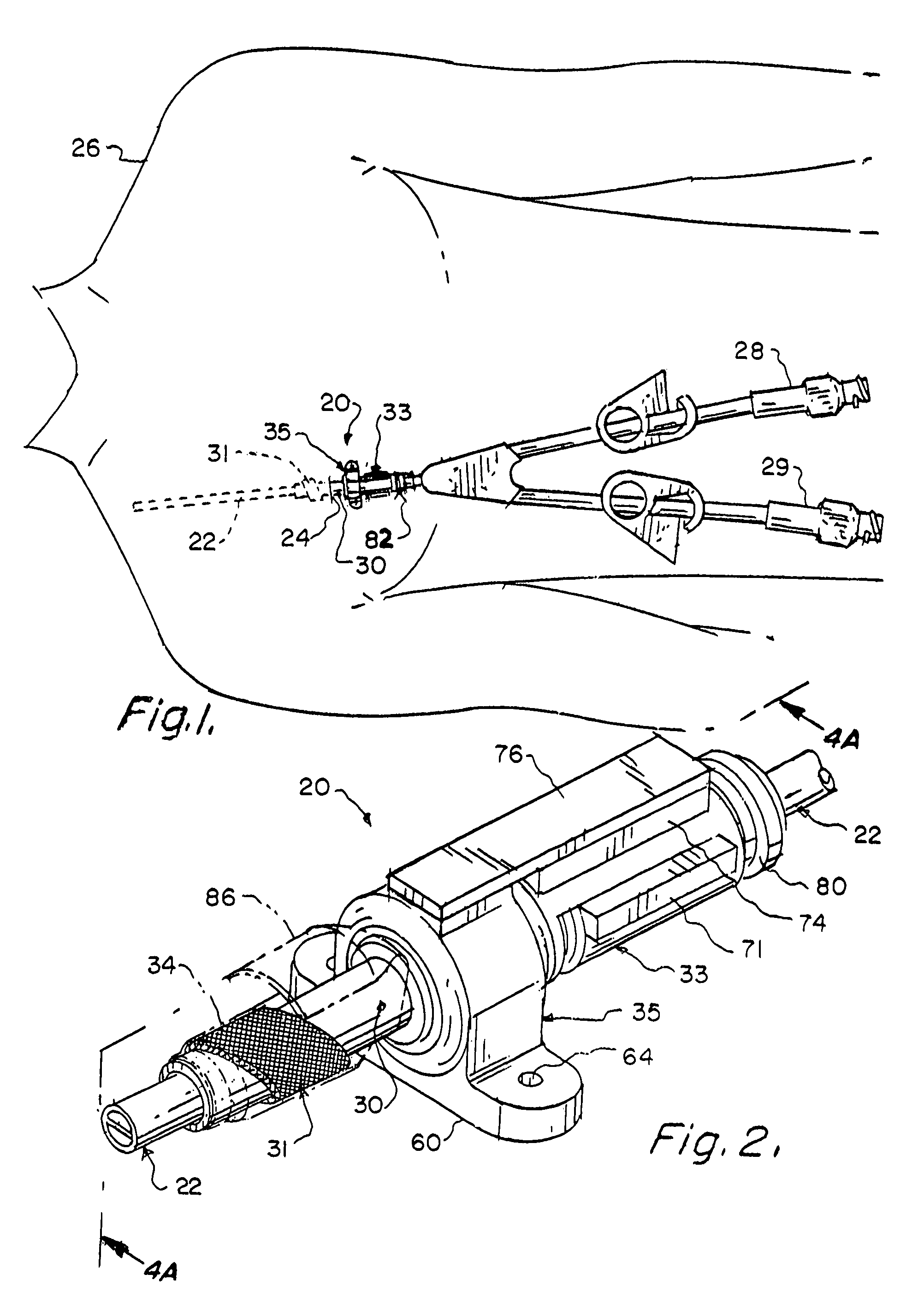
[0028]Various medical regimens relating, for example, to hemodialysis drug infusion, plasmapheresis, etc., use a percutaneously implanted conduit for conveying fluid and / or electric signals to / from an interior body site. The present invention is directed to a method and apparatus for facilitating the implantation and utilization of a percutaneous conduit (e.g., catheter) and for facilitating the positioning, repositioning, and replacement, or exchange, of the catheter.

[0029]FIG. 1 schematically depicts an assembly 20 in accordance with the invention for percutaneously implanting a catheter 22 through an incision 24 in a patient 26 undergoing an exemplary hemodialysis procedure. In such a procedure, a dual lumen catheter 22 is typically used with the two lumens being respectively coupled to separate exterior flow couplers 28 and 29.

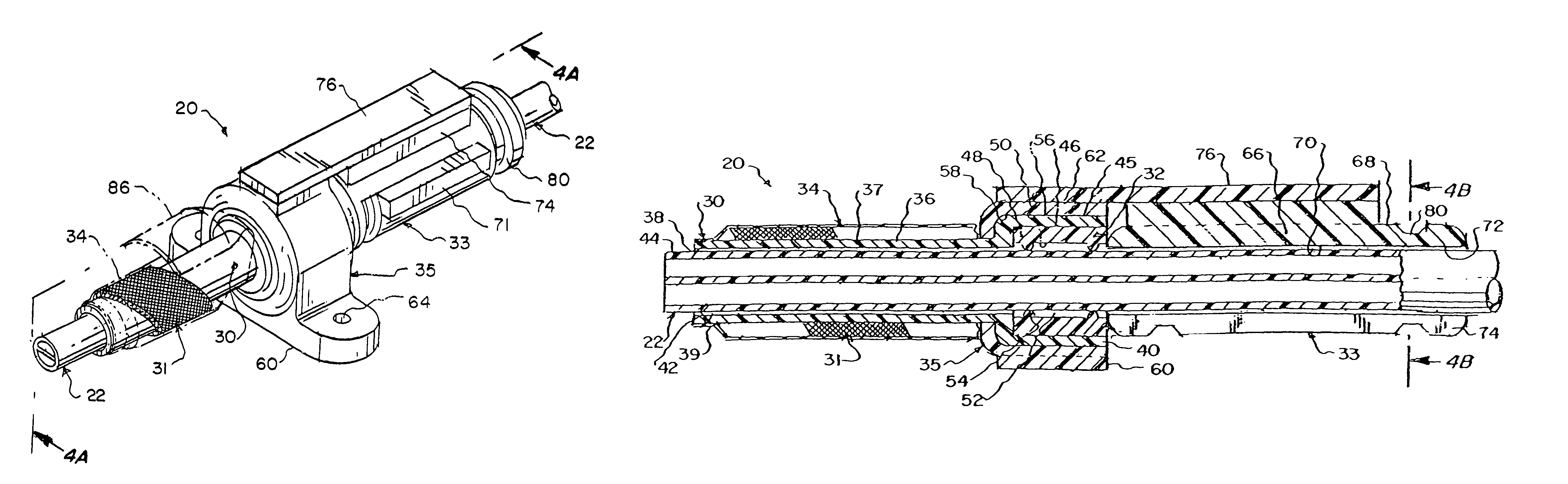
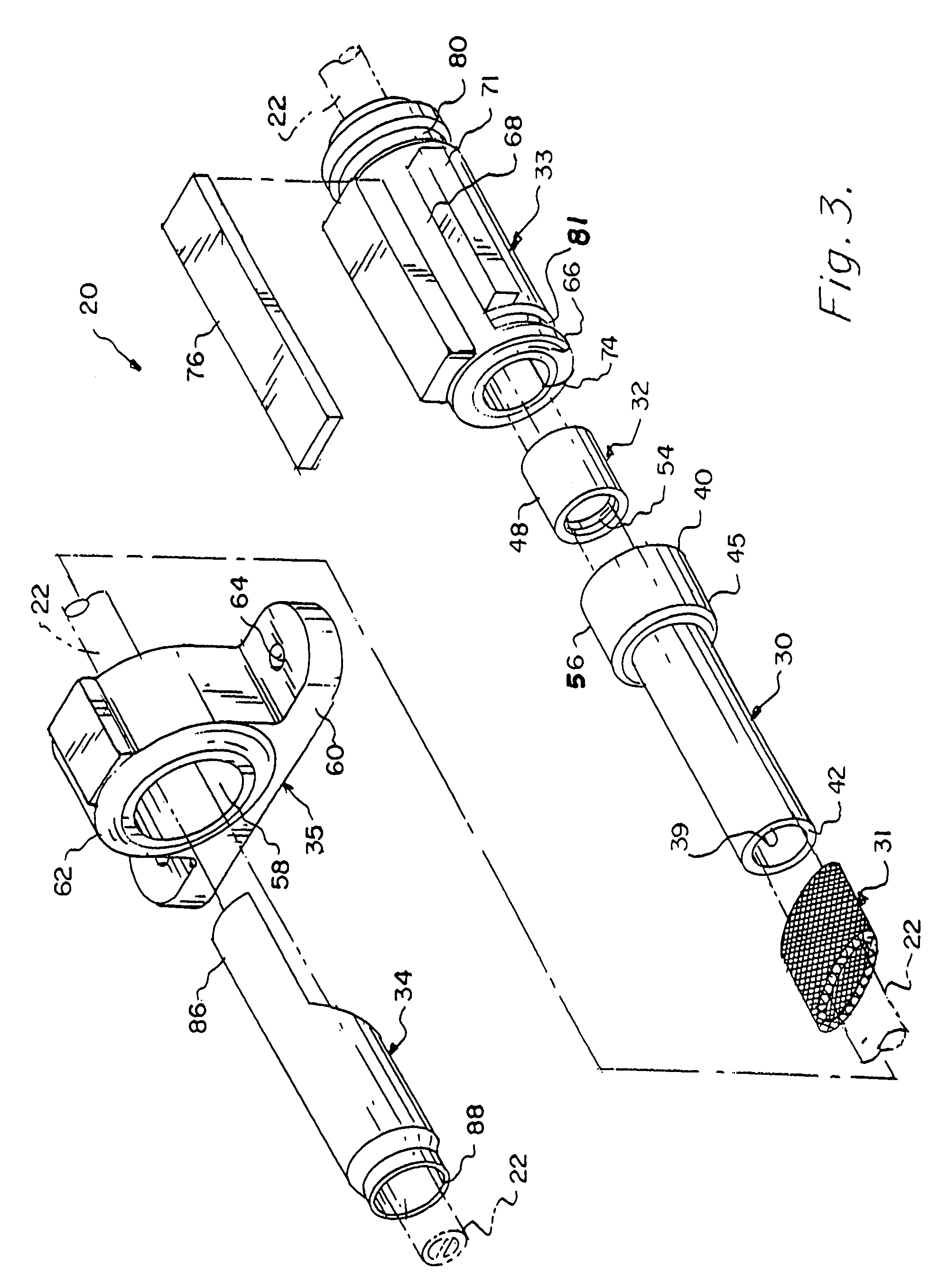
[0030]Attention is now directed to FIGS. 2-4 which depict a preferred catheter assembly 20 in accordance with the present invention. FIG. 3 best shows the...


PUM


Abstract

A medical apparatus and method of use for implanting a catheter in a patient's body which catheter can be easily positioned, repositioned, and replaced. The apparatus includes an elongate sleeve comprising a wall surrounding an interior passageway extending from a sleeve proximal end to a sleeve distal end. The sleeve is intended to be percutaneously implanted through an incision in the patient's skin to place the sleeve distal end subcutaneously. The sleeve distal end outer surface carries porous material intended to contact the patient's dermis to promote tissue ingrowth. The sleeve passageway is dimensioned to snugly accommodate the outer surface of the catheter while permitting the catheter to slide relative to the sleeve. A split ring locking member is selectively operable in an unlocked state for permitting axial and rotational movement of said catheter relative to said sleeve and operable in a locked state for preventing such relative movement.

Description

RELATED APPLICATIONS[0001]This application is a continuation-in-part of U.S. application Ser. No. 10 / 821,383 filed on Apr. 9, 2004 now U.S. Pat. No. 7,604,617, which claims priority based on U.S. Provisional Application 60 / 462,265 filed on Apr. 12, 2003. This application claims priority based on both of said applications and, in addition, on U.S. Provisional Application 60 / 758,137 filed on Jan. 11, 2006. The aforementioned applications are, by reference, incorporated herein.FIELD OF THE INVENTION[0002]This invention relates generally to medical technology and more particularly to a method and apparatus for implanting an elongate conduit, e.g., a catheter or cable, so as to extend through a patient's skin for providing long term access to an interior body site. Embodiments of the invention are useful in a variety of applications, e.g., in hemodialysis procedures to enable a catheter to provide fluid access to a patient's central venous system and / or nerve stimulation procedures in wh...

Claims


Application Information

Patent Timeline
Patent Type & Authority Patents(United States)
IPC IPC(8): A61M5/32A61F2/00A61M1/00
CPCA61M39/0247A61F2/0077A61M2025/0293
Inventor PORTER, CHRISTOPHER H.VIDAL, CLAUDE A.REDMOND, RUSS JMORAN, BYRON L.KALUZNIAK, PAULJANIS, ABRAM D.
Owner INCUMED LLC A NEVADA LIMITED LIABILITY
Why Eureka
Try Eureka