
Vacuum cleaner with large debris receptacle

a vacuum cleaner and large debris technology, applied in the field of vacuum cleaners, can solve the problems of clogging of the air flow system, and affecting the cleaning effect of the vacuum cleaner,

Active Publication Date: 2010-06-29
BISSELL INC
View PDF10 Cites 9 Cited by
  • Summary
  • Abstract
  • Description
  • Claims
  • Application Information

AI Technical Summary

Problems solved by technology

Attempting to use the vacuum cleaner to remove such particles can have deleterious results, such as clogging of the air flow system, jamming of the motor, fracture of vacuum cleaner components, and the like.
However, it is then necessary to transport the particle for disposal, thereby interrupting the vacuuming operation, or find a place to temporarily hold the particle until it can be permanently disposed, such as placing it on an item of furniture, in a user's pocket, or in a user's hand.
This can be burdensome, particularly if several such particles must be removed, unsanitary, and still requires the user to specially dispose of the particle.

Method used


Image

  • Vacuum cleaner with large debris receptacle
  • Vacuum cleaner with large debris receptacle
  • Vacuum cleaner with large debris receptacle

Examples


second embodiment

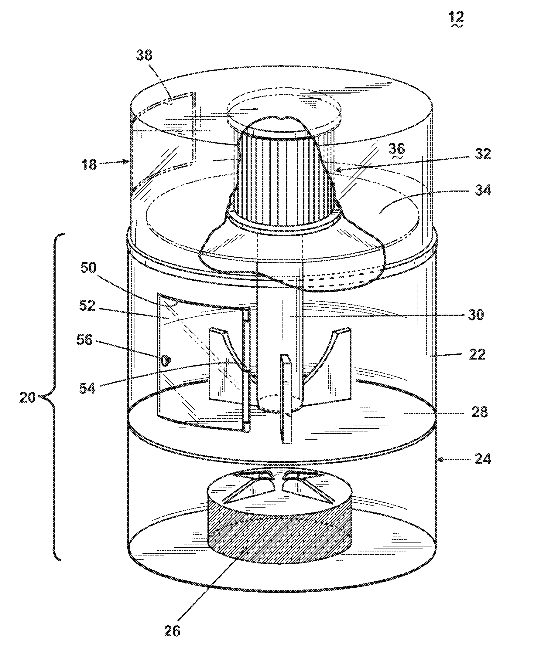
[0024]FIG. 3 illustrates the large debris receptacle in which an opening 60 is provided into the dirt cup 22. However, the opening 60 is fluidly connected to an enclosed chute 62 which extends from the dirt cup 22 along the upright portion 14 to terminate in an opening 63 having a door 64 for opening and closing the chute 62. The dimensions of the openings 60, 63 and the chute 64 are suitable for insertion therethrough of large debris particles. The door 64 can be provided with a gasket for sealing the opening 63 against the flow of air.

third embodiment

[0025]FIG. 4 illustrates the large debris receptacle in which an opening 70 is provided into the dirt cup 22. A funnel 72 is attached to the side of the dirt cup 22 and fluidly connected to the interior of the dirt cup 22 through the opening 70. The funnel 72 has an opening 74 having dimensions, with the opening 70, suitable for insertion therethrough of large debris particles. Alternatively, the opening 74 can be provided with a door (not shown).

fourth embodiment

[0026]FIG. 5 illustrates the large debris receptacle comprising a container 80 such as a small receptacle, mesh container, mesh bag, and the like, attached to an upper portion of the upright portion 14. The container 80 is not connected to the dirt cup 22. The container 80 can be provided with a movable cover 82 for closing the container 80, and can be sized to accommodate a preselected volume of large debris particles that may be encountered during vacuuming operations. The container 80 is removably attached to the upright portion 14 to facilitate emptying the container 80 of its contents.

[0027]FIG. 5 also illustrates an external opening 84 in the working air conduit 42 for introduction into the working air conduit of larger debris that is not ordinarily picked up by the suction nozzle 40. The external opening 84 is selectively sealed with a hinged door 86 in a manner disclosed for the door 52 in the embodiment of FIG. 2.

[0028]The large debris receptacle described herein provides a...


PUM

PropertyMeasurementUnit
sizeaaaaaaaaaa
weightaaaaaaaaaa
dimensionsaaaaaaaaaa

Abstract

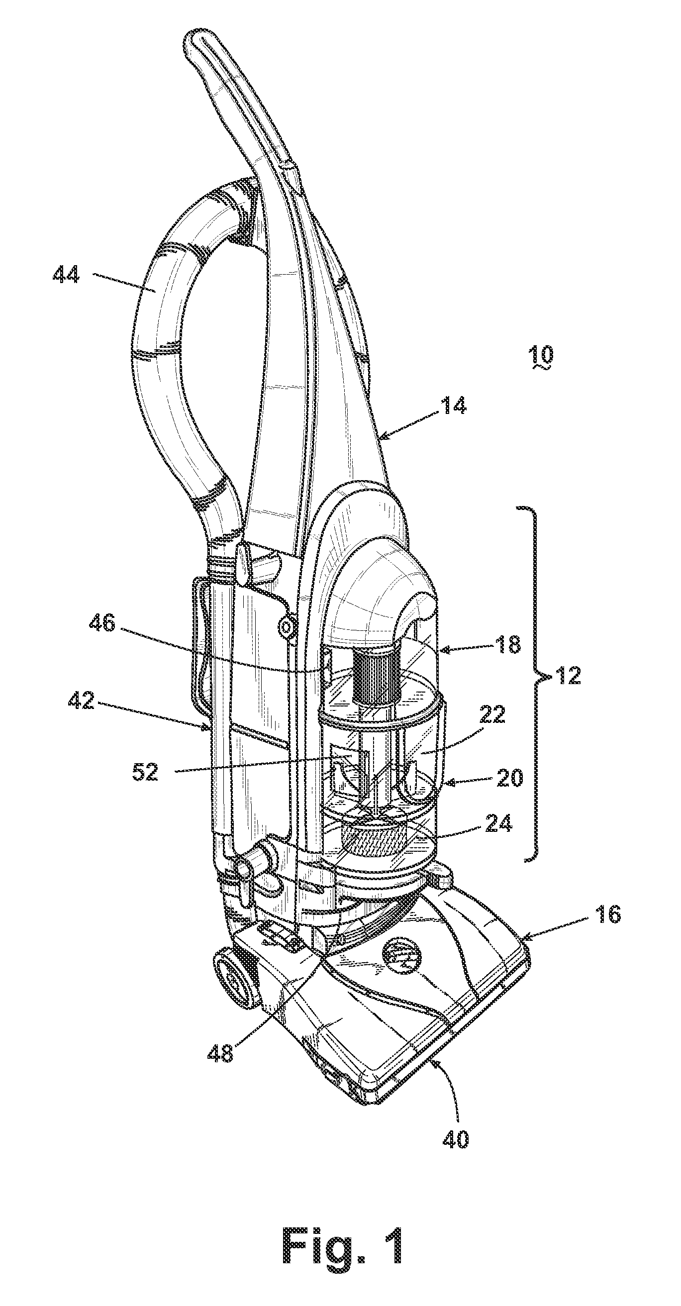
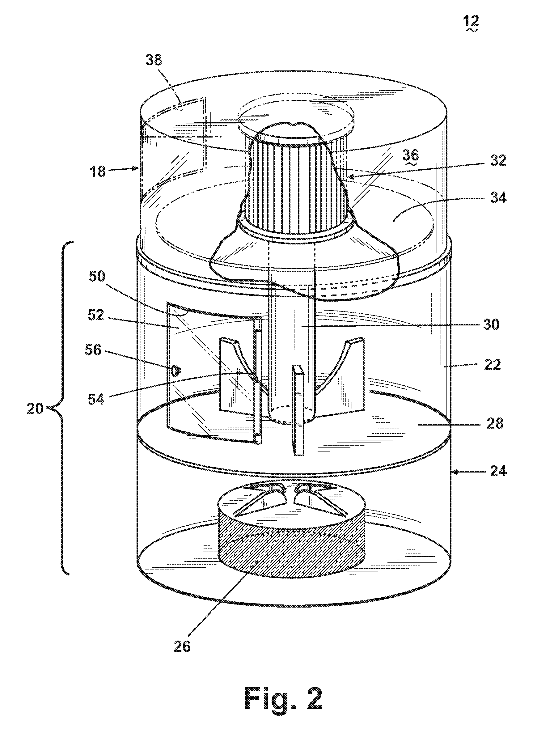
A vacuum cleaning machine comprising a housing that includes a suction nozzle that is adapted to move along a surface to be cleaned and a receptacle coupled to the housing for holding particles removed from the surface during operation of the vacuum cleaning machine. The receptacle is provided with an external opening for the introduction of debris particles therein which are not ordinarily removable from the surface through the suction-generating apparatus. The vacuum cleaning machine can be an upright vacuum cleaning machine and the receptacle can be mounted to the handle. The receptacle can also be incorporated into a dirt cup in a cyclone separator module.

Description

BACKGROUND OF THE INVENTION[0001]1. Field of the Invention[0002]The invention relates to a vacuum cleaner. In one of its aspects, the invention relates to a vacuum cleaner with a facility for collecting large debris particles that are not ordinarily picked up by the suction nozzle.[0003]2. Description of the Related Art[0004]There is typically an upper limit to the size and weight of the dirt and debris particles that can be removed by the vacuum cleaner from a surface to be cleaned. Attempting to use the vacuum cleaner to remove such particles can have deleterious results, such as clogging of the air flow system, jamming of the motor, fracture of vacuum cleaner components, and the like.[0005]Alternatively, the particle can be removed by hand prior to passing the vacuum cleaner over the surface. However, it is then necessary to transport the particle for disposal, thereby interrupting the vacuuming operation, or find a place to temporarily hold the particle until it can be permanent...

Claims


Application Information

Patent Timeline
Patent Type & Authority Patents(United States)
IPC IPC(8): A47L9/10
CPCA47L9/1683
Inventor CARR, ADAM G.MAHAFFY, DONALD J.
Owner BISSELL INC
Learn More