Method for designing an orbit of a spacecraft

a spacecraft and orbit design technology, applied in the field of spacecraft orbit design, can solve the problems of inability to maintain the position of the spacecraft, large orbit, and inability to achieve the effect of avoiding the abandonment of most merits,

Inactive Publication Date: 2010-06-29
JAPAN AEROSPACE EXPLORATION AGENCY
View PDF4 Cites 6 Cited by
  • Summary
  • Abstract
  • Description
  • Claims
  • Application Information

AI Technical Summary

Problems solved by technology

However, the natural halo orbit disadvantageously leads to an extraordinarily large orbit which must depart from a co-linear line connecting two celestial bodies.
Because of this, the merit associated with the halo orbits, that is, no maintenance of the position of a spacecraft is needed, is inevitably lost, if the trajectory size is controlled and maintained artificially.
Currently a number of spacecrafts take natural halo orbits, for example, around the L2 point to make astronomical observations, but the merits characteristic of the halo orbits are not yet fully made use of, leaving the most merits abandoned.
This might be still possible, however, if performed via chemical propulsion engines, a tremendous amount of fuel is required and is concluded far from practical.
If a spacecraft launched into an improper orbit and makes correction via a chemical propulsion, a considerable fuel is needed to reach a proper orbit, and such will significantly affect the operation life of the spacecraft, and causes a lot of operational restriction.
And if a spacecraft orbit is corrected via an electric energy of a battery, fuel may be saved, but, battery energy is too small to have an intended amount of acceleration to a proper orbit.
Because of these difficulties, having a concise halo orbit around L1 or L2 has still remained difficult by now.

Method used


Image

  • Method for designing an orbit of a spacecraft
  • Method for designing an orbit of a spacecraft
  • Method for designing an orbit of a spacecraft

Examples


Embodiment Construction

[0029]The preferred embodiments of the invention will be described in detail below with reference to the attached drawings.

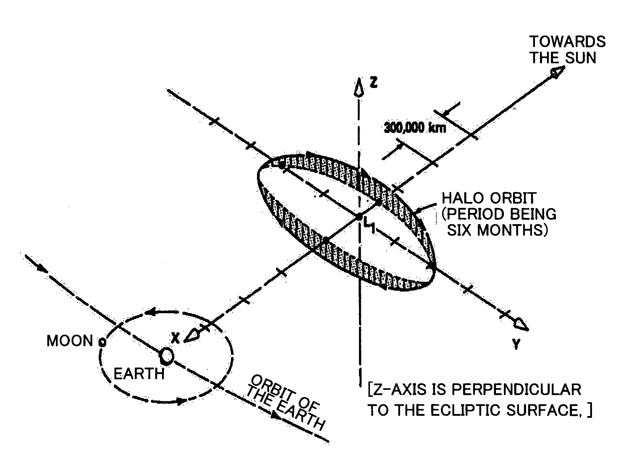
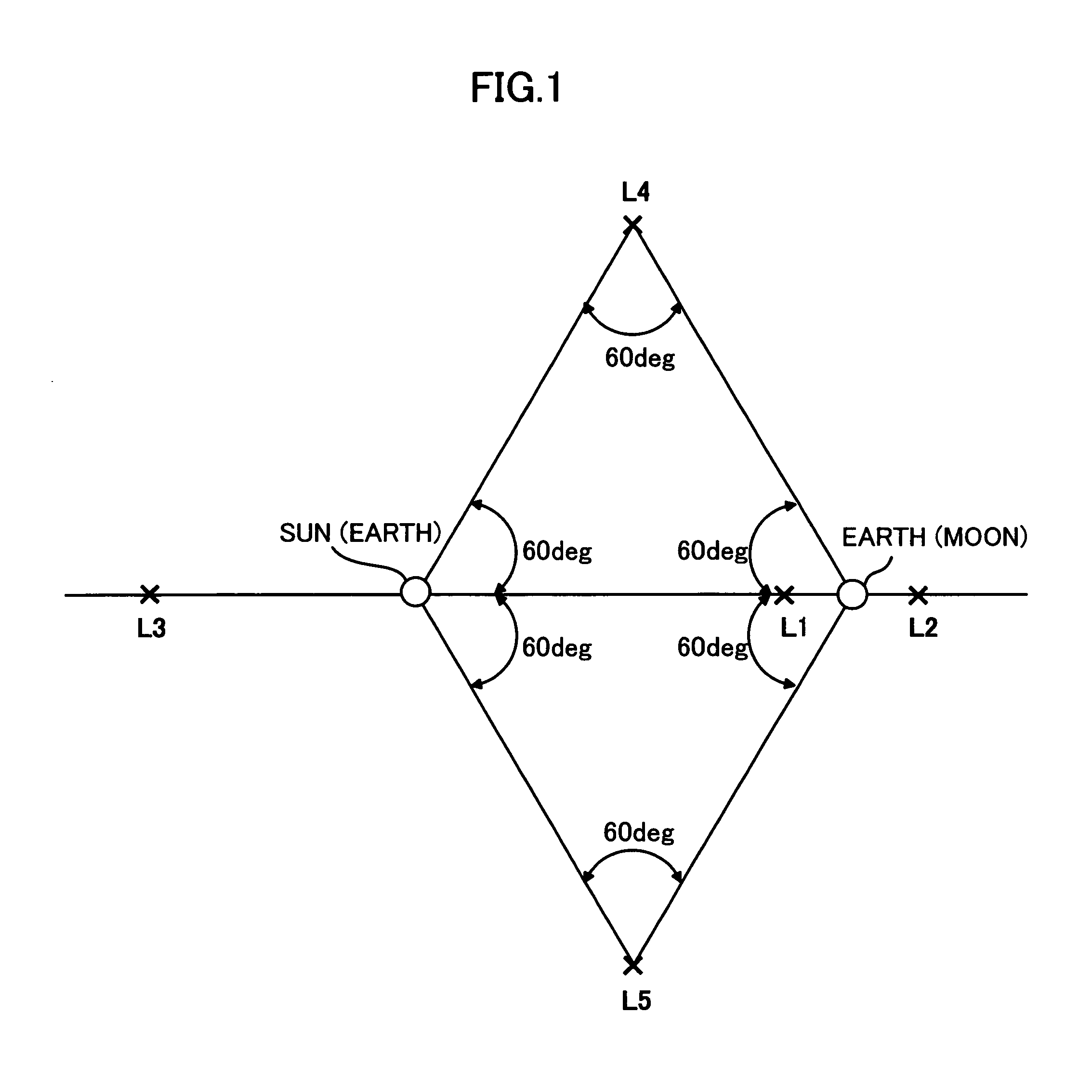
[0030]Take, as an example, a system comprising two celestial bodies (for example, the Earth and the Moon) having a comparatively large mass, and a body having a comparatively small mass (for example, artificial satellite) where both bodies revolve around the bury-center, a center of masses of the two large bodies system, in a circular orbit, and the small body resides close to the former body. It has been known that there are five equilibrium points along the line connecting the two bodies where the small body can be stationary relative to the other two larger bodies. They are known as Lagrange points, and called Lagrange points L1, L2, . . . , L5. FIG. 1 illustrates five Lagrange points with particular reference to their positions relative to the two larger bodies. As shown in the figure, the points L1 to L3 are located on a line connecting the two celestial bo...


PUM


Abstract

A method is disclosed for designing an orbit of a spacecraft which allows the spacecraft to take a small-radius halo orbit near a Lagrange point while avoiding the prohibited zone where the spacecraft may be shadowed or might be prevented from making communication. The method makes it possible to have a closed orbit although being similar to a Lissajous orbit, under a restricted condition where a propulsion force magnitude applied to a spacecraft is fixed, and where it rotates at a constant angular velocity, based on the equation of motion close to a Lagrange point. The method also provide a theory for guiding / controlling the orbit of a spacecraft, that is, the embodiment of the above orbit design method.

Description

CROSS-REFERENCE TO RELATED APPLICATIONS[0001]The present patent application claims priority from Japanese Patent Application No. 2005-210266, filed on Jul. 20, 2005.FIELD OF THE INVENTION[0002]The present invention relates to a method for designing an orbit of a spacecraft to move in a cosmic space, particularly to a method for designing an orbit of a spacecraft which enables the spacecraft to be on a small-radius halo orbit near a Lagrange point while avoiding the prohibited zone where the spacecraft may be shadowed or might be prevented from making communication.BACKGROUND OF THE INVENTION[0003]Take, as an example, a system consisting of two celestial bodies where both bodies turn around the bury-center, a center of masses of two bodies, taking a circular orbit like the Earth and the Sun, and a vary light third body flying in the system. It has been known that there are five equilibrium points in the system where gravity from those two bodies and a centrifugal force acting on a th...

Claims


Application Information

Patent Timeline
Patent Type & Authority Patents(United States)
IPC IPC(8): B64G1/10
CPCB64G1/26B64G1/242
Inventor KAWAGUCHI, JUNICHIROTARAO, KOHTA
Owner JAPAN AEROSPACE EXPLORATION AGENCY
Why Eureka
Try Eureka