Annular pressure monitoring during hydraulic fracturing

a technology of annular pressure monitoring and hydraulic fracturing, which is applied in the direction of fluid removal, sealing/packing, and wellbore/well accessories, etc., can solve the problem of pressure also rising in the annulus going back

Active Publication Date: 2010-07-06
BAKER HUGHES INC
View PDF12 Cites 17 Cited by
  • Summary
  • Abstract
  • Description
  • Claims
  • Application Information

AI Technical Summary

Problems solved by technology

The problem that arises occurs when the formation has what's called a sand out where flow into the formation declines dramatically because the proppant creates a barrier to further fluid progress into the formation.
The problem with rising pressure at the formation is that the pressure also rises in the annulus going back to the surface.

Method used


Image

  • Annular pressure monitoring during hydraulic fracturing
  • Annular pressure monitoring during hydraulic fracturing

Examples


Embodiment Construction

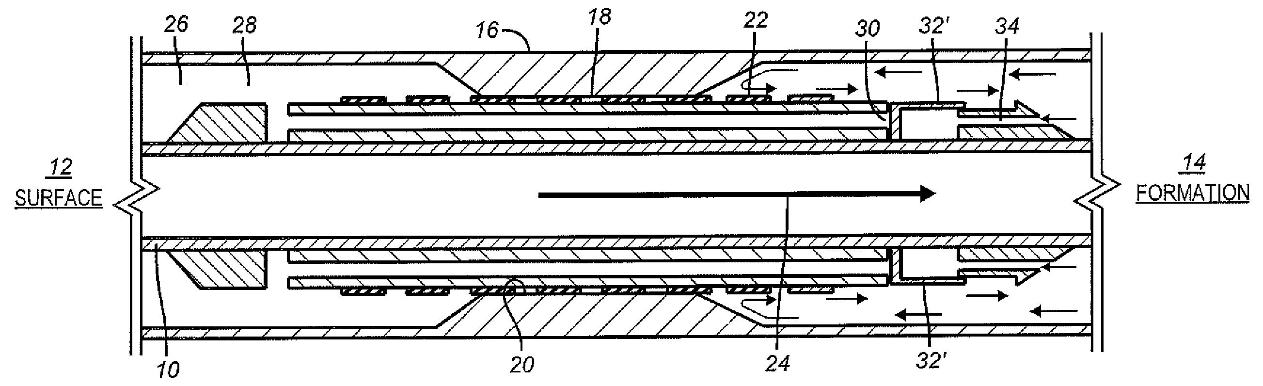
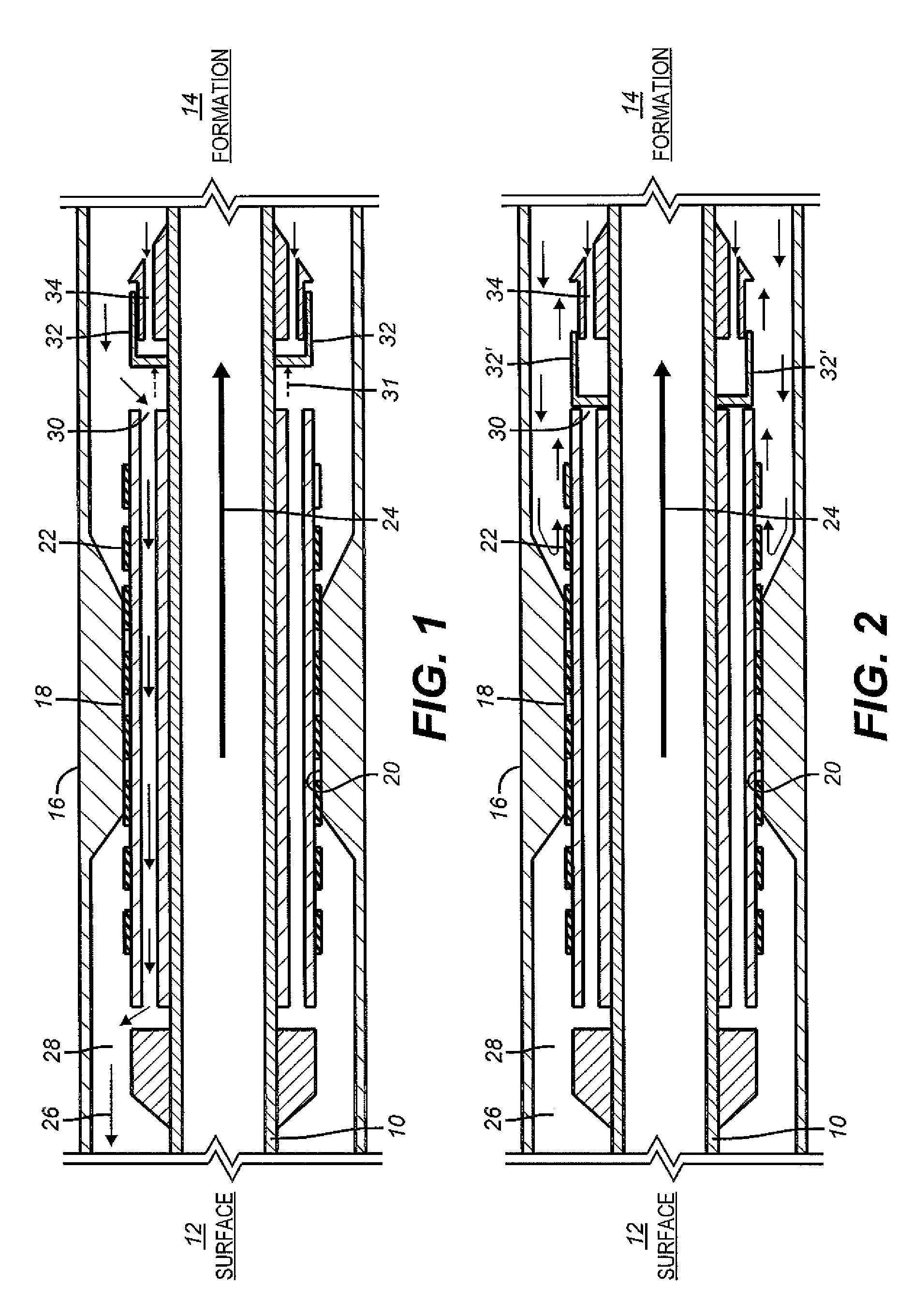
[0006]FIG. 1 shows a workstring 10 that extends from the surface 12 to the formation 14 being treated. The wellbore preferably is cased with casing 16 such that comprises at least one seal point such as a packer or a seal bore 18. The workstring 10 has an external bypass 20 that further features one or more exterior seals 22 designed to fit in the seal bore 18. During normal operations, pressure at surface 12 causes flow 24 down to the formation 14. Generally, proppant slurry is used but the formulation being pumped can vary with the makeup of the formation and the compositions being pumped are well known in the art. As the pumping continues fracturing of the formation 14 can occur with some of the solids in the slurry working their way into newly created fissures from the pressures used in delivering the slurry downhole. As a way of monitoring the pressure at the fracture location from the surface, return flow 26 goes through the bypass 20 and up the annular space 28 to the surface...


PUM


Abstract

A pressure or flow responsive valve is provided in a hydraulic fracturing assembly so that if the formation sands out during proppant pumping and pressure in the bypass to the annulus around the work string rises, the bypass is closed by the valve to prevent overpressure of lower pressure rated components further uphole from the formation being treated. These components could be large casing or the blowout preventer assembly.

Description

FIELD OF THE INVENTION[0001]The field of the invention is a technique for protecting an annulus leading to the surface from overpressure beyond the limits of tubulars or blowout preventers particularly during a hydraulic fracturing operation.BACKGROUND OF THE INVENTION[0002]Hydraulic fracturing is performed through a work string that leads from the surface to the desired formation. At some point the work string goes through a seal point and could contain a bypass through that point so that the pressure at the formation can be determined by surface measurements of the annulus pressure that is communicated to the surface through the bypass of the work string that extends through the seal point. The seal point may be a packer or a seal bore. Hydraulic fracturing involves pumping proppant slurry into the wellbore through the work string to the desired formation. The work string terminates above or uphole from the formation being treated. The fluid is forced into the formation to fractur...

Claims


Application Information

Patent Timeline
Patent Type & Authority Patents(United States)
IPC IPC(8): E21B33/12E21B43/26
CPCE21B34/08E21B43/267
Inventor JOHNSON, MICHAEL H.
Owner BAKER HUGHES INC
Why Eureka
Try Eureka