Friction stir welding device

a technology of friction stir and welding device, which is applied in the direction of soldering apparatus, welding device, manufacturing tools, etc., can solve the problems of increasing the strength of the driving means, increasing the cost of the equipment and installation space, and inevitably large equipment cost and installation space, so as to improve the usability and facilitate welding preparation. , the effect of reducing the time required for welding preparation

Active Publication Date: 2010-07-06
KAWASAKI HEAVY IND LTD
View PDF31 Cites 78 Cited by
  • Summary
  • Abstract
  • Description
  • Claims
  • Application Information

AI Technical Summary

Benefits of technology

[0012]Therefore, an object of the present invention is to provide a friction stir welding device capable of flexibly dealing with various articles to be welded regardless of the size and shape thereof.

Problems solved by technology

Therefore, the equipment cost and installation space are also made inevitably large.
Further, the own weight of the device itself is made heavy due to enlargement, so that it is necessary to increase the strength of the driving means.
Thus the capital investment required for manufacture and introduction thereof is increased inevitably.
Further, it is difficult for one friction stir welding device to flexibly deal with articles to be welded in different shapes.
Therefore, even if the article to be welded is large, the friction stir welding device is not necessarily enlarged.
Further, according to the related art, when the members to be welded are formed in a curved surface shape, the adjustment of the FSW head in the vertical direction is complicated.

Method used


Image

  • Friction stir welding device
  • Friction stir welding device
  • Friction stir welding device

Examples


second embodiment

[0177]FIG. 24 is a sectional view showing a modification of the welding device 100 of the Although the screw shaft 110 of the ball screw 109 is rotated by the power generation source 106 in FIG. 23, the power for rotating the screw shaft 110 may be given by an operator. In this case, a handle 112 for rotating the screw shaft 110 is rotated by the operator, thus the cylinder support section 42 can be moved on both sides in the transverse direction Y.

[0178]FIG. 25 is a drawing of an enlarged part of a welding device 120 of the third embodiment of the present invention. The welding device 120 of the third embodiment includes a detection means 121 for detecting the position of the welding line 29 of the article 23 and a regulation means 122 for controlling movement of the tool holding section 31 so as to make the immersion amount into the article 23 by the welding tool 24 coincide with a predetermined immersion amount.

[0179]The welding device 120 of the third embodiment, with respect t...

ninth embodiment

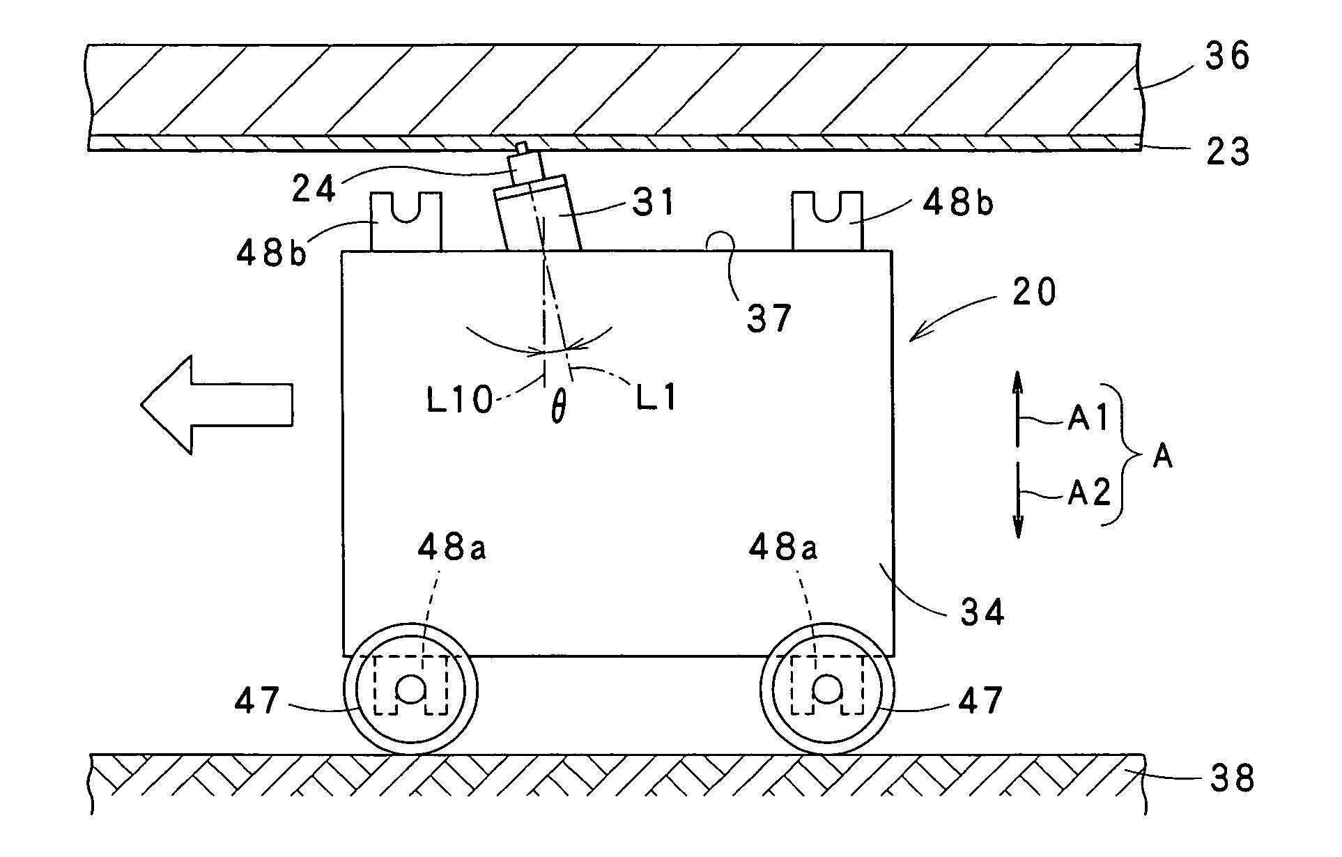
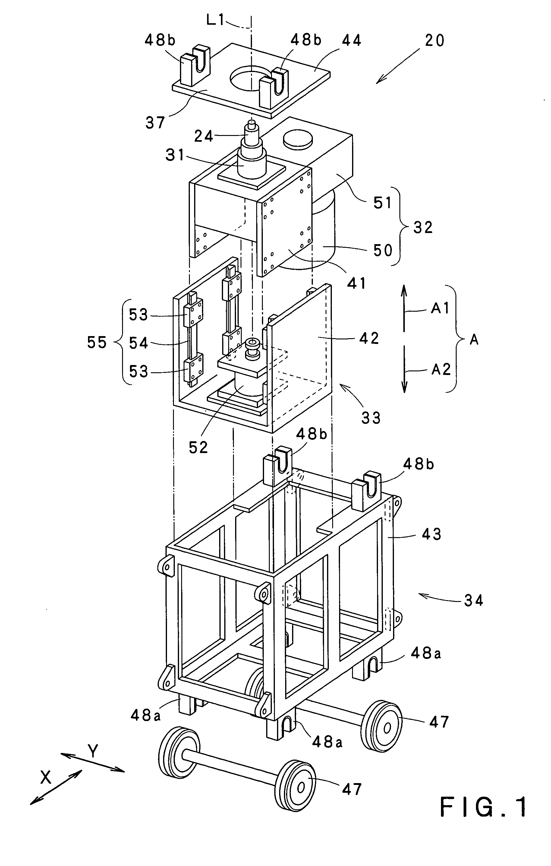
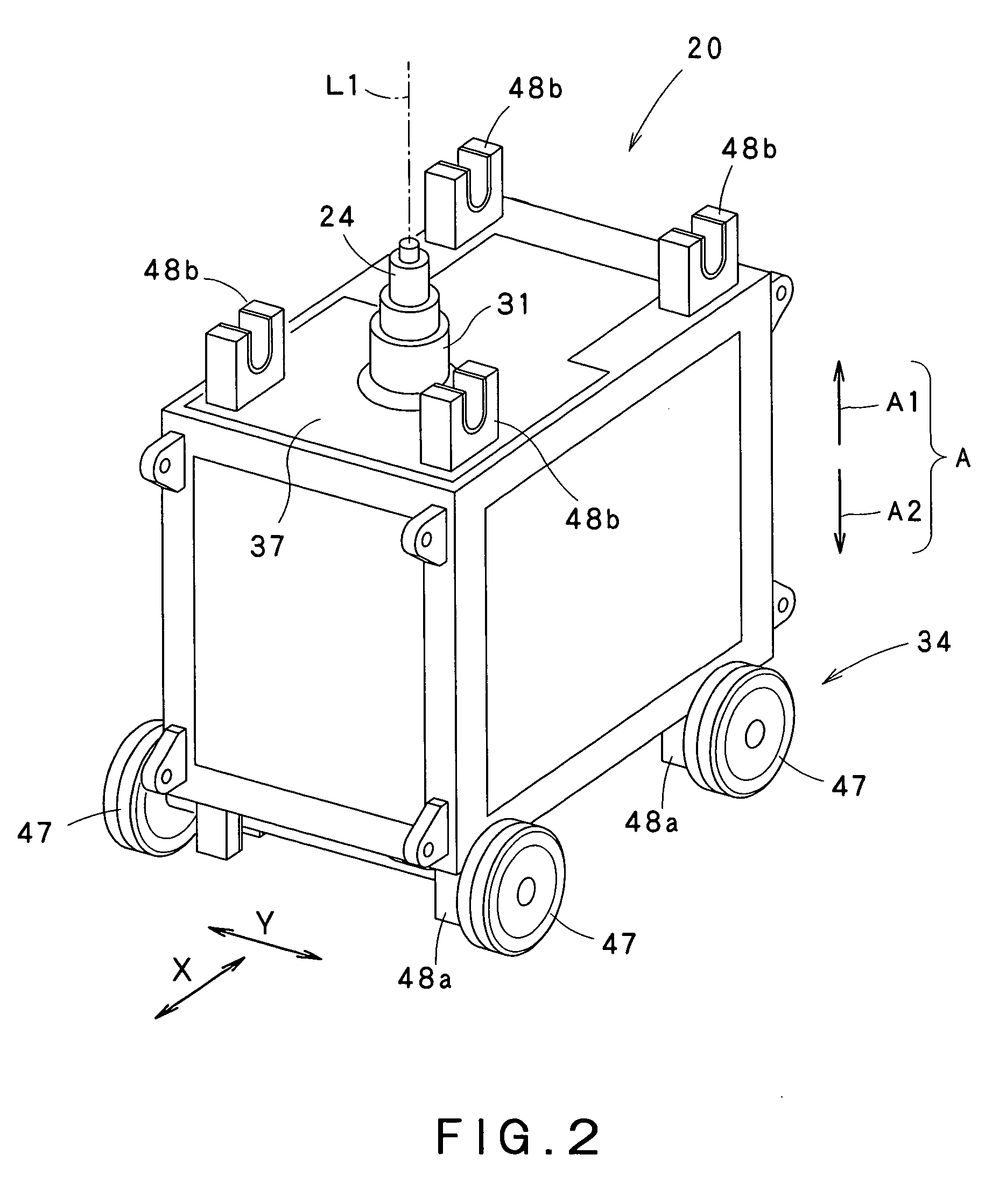
[0205]FIG. 33 is a side view showing a welding device 720 of the present invention and FIG. 34 is a plan view showing the welding device 720. The welding device 720 has the same constitution as that of the welding device of each of the embodiments aforementioned. For the same constitution, the explanation is simplified or omitted and the same reference numerals are assigned.

[0206]The welding device 720 includes the tool holding section 31 for holding the welding tool 24, the rotation driving means 32 for driving the tool holding section 31 to rotate round the reference axial line L1, the air cylinder 52 for moving the tool holding section 31 along the reference axial line L1, the car body 34 for loading the tool holding section 31, rotation driving means 32, and air cylinder 52, the traveling means 35 for traveling the car body 34, and the control means 60 for controlling the rotation driving means 32, traveling means 35, and air cylinder 52. The welding device 720 can weld the two ...

third embodiment

[0220]FIG. 37 is a sectional view showing the guide body 90. As shown in FIGS. 36 and 37, the guide body 90 may be fixed to the article 23 or fixing object 210 by vacuum suction. In this embodiment, the guide body 90 is fixed to the article 23 by vacuum suction. In this case, the guide body 90 includes a body part 214 having the fixed portion 200 and guide portion 201, a suction means 211, and a connection body 212 for fixing the body part 214 and suction means 211.

[0221]In this embodiment, the suction means 211 is realized by a vacuum suction pad. The suction pad, when it is in contact with the article 23, forms a closed space 217 between the article 23 and itself. And, air filled in the closed space 217 is suctioned by a suction source 213, thus the suction pad is adhered to the article 23. The suction means 211 and the body part 214 are connected by the connection means 212, thus the body part 214 is fixed to the article 23. When the body part 214 is fixed to the article 23 by th...


PUM

PropertyMeasurementUnit
inclination angleaaaaaaaaaa
thicknessaaaaaaaaaa
heightaaaaaaaaaa

Abstract

A friction stir welding device for welding an article by means of a welding tool, includes: a tool holding section configured to hold the welding tool and rotate round a predetermined reference axial line; rotation driving unit configured to drive the tool holding section to rotate round the reference axial line; movement driving unit configured to drive the tool holding section to move along the reference axial line; and a car body loaded with the tool holding section, the rotation driving unit and the movement driving unit, the car body being configured to travel above or below the article.

Description

CROSS REFERENCE TO RELATED APPLICATIONS[0001]This application is based upon the prior Japanese Patent Application No. 2005-180702 filed on Jun. 21, 2005, the entire contents of which are incorporated herein by reference.BACKGROUND[0002]1. Field of the Invention[0003]The present invention relates to a friction stir welding device for welding an article to be welded by frictionally stirring the same.[0004]2. Description of the Related Art[0005]An article to be welded forms a joint section by butting two members to be welded. The friction stir welding device fluidizes and stirs the joint section of the article to be welded due to frictional heat by a welding tool, thereby welds the two members to be welded.[0006]FIG. 51 is a perspective view showing a friction stir welding device 1 of the first related art. The friction stir welding device 1 of the first related art includes a friction stir welding (FSW) head 2 and a table 3. The FSW head 2 is provided with a welding tool 4 and rotates...

Claims


Application Information

Patent Timeline
Patent Type & Authority Patents(United States)
IPC IPC(8): B23K20/12
CPCB23K20/1245B23K37/0217B23K37/0294
Inventor KOGA, SHINJIINUZUKA, MASAYUKINISHIDA, HIDEHITOOTSUKI, YASUONAKASHIMA, KATSUMINISHIYAMA, GOROYAMAZAKI, KENTAROOHTA, KOUICHI
Owner KAWASAKI HEAVY IND LTD
Why Eureka
Try Eureka