Drum lid removal tool

a technology of drum lids and tools, applied in the field of drum lid removal tools, can solve the problems of limiting the ability to reuse drums or lids

Inactive Publication Date: 2010-08-24
SAVANNAH RIVER NUCLEAR SOLUTIONS
View PDF20 Cites 8 Cited by
  • Summary
  • Abstract
  • Description
  • Claims
  • Application Information

AI Technical Summary

Problems solved by technology

Most often the drum lids are removed with a hammer and chisel and, as a result, the lid and drum rim are scarred or dented limiting the ability to reuse the drum or the lid.
One problem, as mentioned, is to readily open the container so that the lid is not destroyed even when there is a protruding edge on the lid.
However, all of these prior art devices are used where there is a protruding tab or edge that is readily gripped.

Method used


Image

  • Drum lid removal tool
  • Drum lid removal tool
  • Drum lid removal tool

Examples


Embodiment Construction

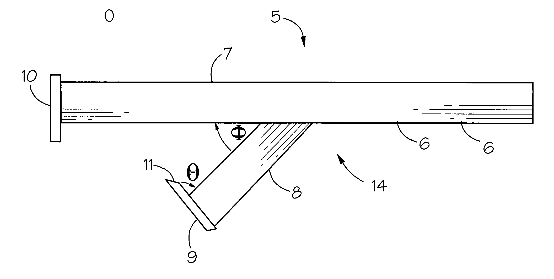
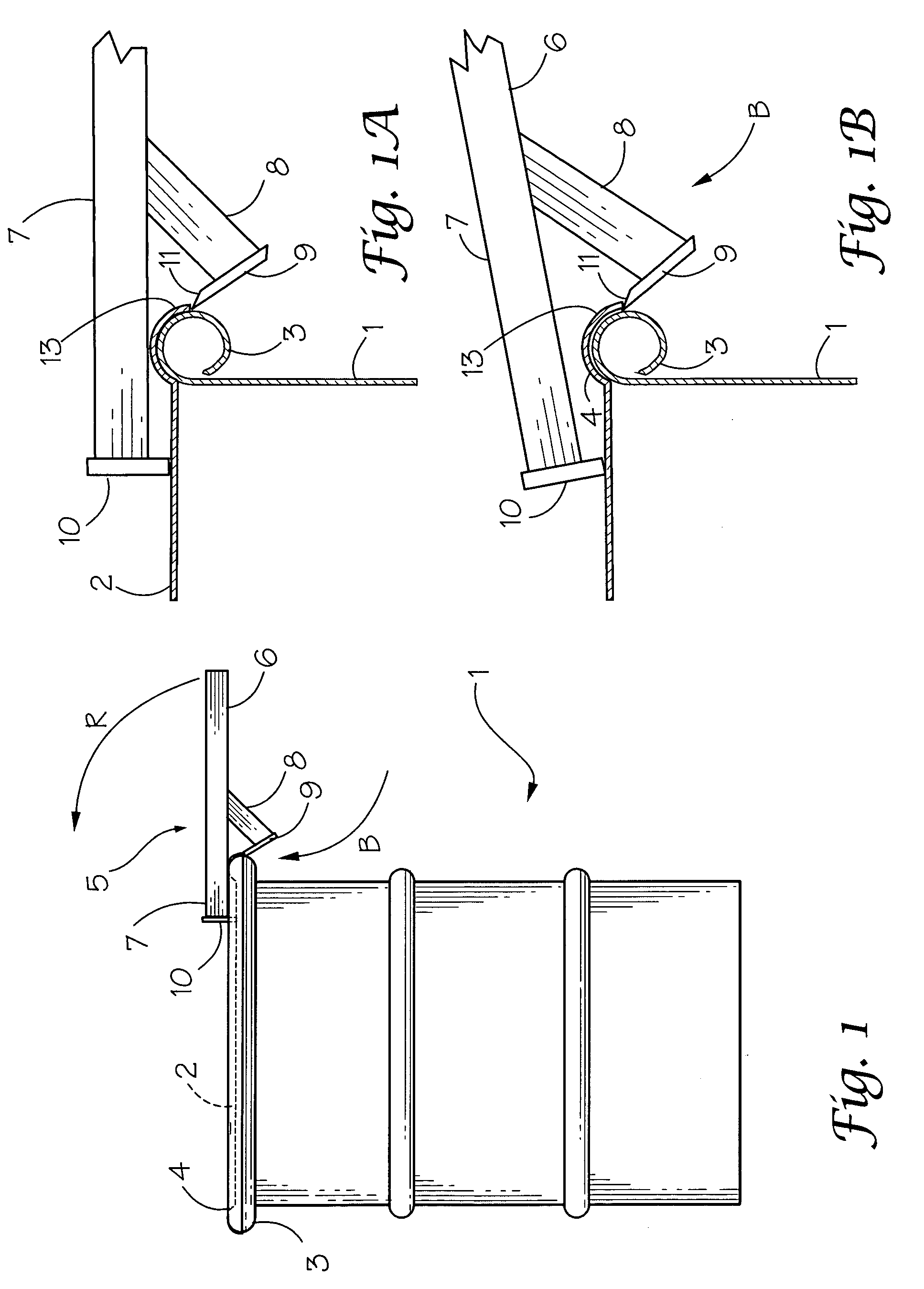
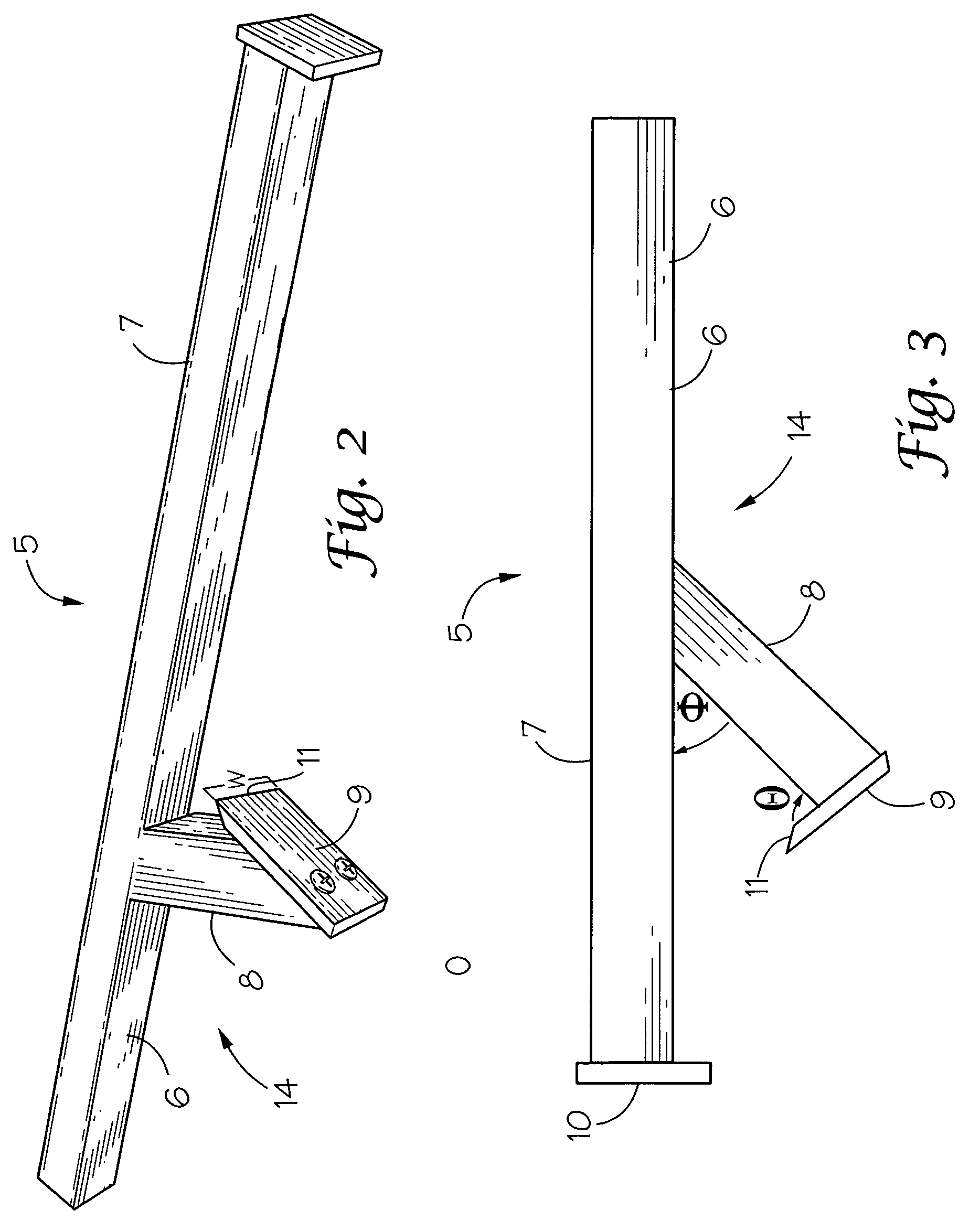
[0018]Referring first to FIG. 1, the drum lid removal tool 5 has been developed to fill the need to open a metal drum 1 having a clamping ring lid 2. The sealing means is a circular rolled drum surface or rim 3 at the opening of the top of the drum. The drum lid 2 contains an identically shaped half circle groove 4 that mates over the entire surface of the drum rolled edge 3. The lid is held in place on the drum by forcibly clamping the grooved drum ring 4 over rim 3. In other words, the drum ring uses the half circle channel or groove 4 to clamp over the transition area between the drum rolled edge and the edge of the drum lid causing an extremely close tolerance or a gap less than 0.025 inches between the drum rolled edge and the drum lid. In FIG. 1A, this is the space between rolled edge 3 and grooved lip 13 of the lid 2. This extremely close gap tolerance is unlike surfaces or ridges or protruding edges that may be grasped to remove lids from other types of containers.

[0019]In F...


PUM


Abstract

A tool for removing the lid of a metal drum wherein the lid is clamped over the drum rim without protruding edges, the tool having an elongated handle with a blade carried by an angularly positioned holder affixed to the midsection of the handle, the blade being of selected width to slice between lid lip and the drum rim and, when the blade is so positioned, upward motion of the blade handle will cause the blade to pry the lip from the rim and allow the lid to be removed.

Description

FEDERALLY SPONSORED RESEARCH[0001]The U.S. Government has rights in this invention pursuant to contract number DE-AC O9-96SR18500 between the U.S. Department of Energy and Washington Savannah River Company LLC.FIELD OF THE INVENTION[0002]This invention relates to a tool for removing the lids of open head metal drums wherein the lid forms a clamping ring that clamps to the drum rim leaving a very small gap between the lid and drum rim with no protuberances.BACKGROUND OF THE INVENTION[0003]In the shipping industry there are two types of metal drums in general use. These are open head drums and closed head, the closed head being those with bung holes for removal of the drum contents through the side of the drum. The present invention is directed to open head drums and for these there are generally two types of drum rings for securing the lid to the drum. These two types are one-piece and two-piece rings and the present invention applies to one-piece rings.[0004]The mechanism used to se...

Claims


Application Information

Patent Timeline
Patent Type & Authority Patents(United States)
IPC IPC(8): B67B7/16
CPCB67B7/14
Inventor PELLA, BERNARD M.SMITH, PHILIP D.
Owner SAVANNAH RIVER NUCLEAR SOLUTIONS
Why Eureka
Try Eureka