
Recessed light housing with a rotatable aperture

a recessed light and aperture technology, applied in the field of recessed lighting, can solve the problems of increasing the work necessary for proper installation, the wear and damage of the support structure and the difficulty of achieving the recessed light assembly, etc., to achieve the effect of convenient and efficient manner

Inactive Publication Date: 2010-11-16
USAI LLC
View PDF17 Cites 28 Cited by
  • Summary
  • Abstract
  • Description
  • Claims
  • Application Information

AI Technical Summary

Benefits of technology

"The present invention is a recessed light assembly with a rotatable aperture plate. The assembly includes an enclosure that can be mounted in a variety of ways, such as in a ceiling or wall. The enclosure has an opening and an illumination element inside. The assembly also has a rotating aperture plate with an illumination aperture that can be rotated to different positions. The user can adjust the rotational alignment of the aperture plate without needing to disengage the assembly from the support structure. The illumination element is fixed relative to the rotating aperture plate, so the rotation of the aperture plate causes the illumination element to rotate as well. The assembly also has a removable mechanism to selectively fix the aperture plate in a specific rotational alignment relative to the enclosure. This allows for precise alignment of the aperture plate with the enclosure."

Problems solved by technology

Obtaining a desired (i.e., parallel or particular alternate) alignment of a non-round illumination aperture of a recessed light assembly is often difficult to accomplish when securing the recessed light assembly within a ceiling or wall because the support structure may be out of alignment or may not have the desired particular alignment and / or the light assembly may be installed improperly.
Further, aligning a non-round illumination aperture in a particular alternate alignment (e.g., 45 degrees from parallel to a wall) is often not possible or is difficult and / or imprecise using a conventional recessed light assembly having a fixed illumination aperture.
This increases the work necessary for proper installation, the costs of such installation, and the wear and damage to the support structure and recessed light assembly.

Method used


Image

  • Recessed light housing with a rotatable aperture
  • Recessed light housing with a rotatable aperture
  • Recessed light housing with a rotatable aperture

Examples


Embodiment Construction

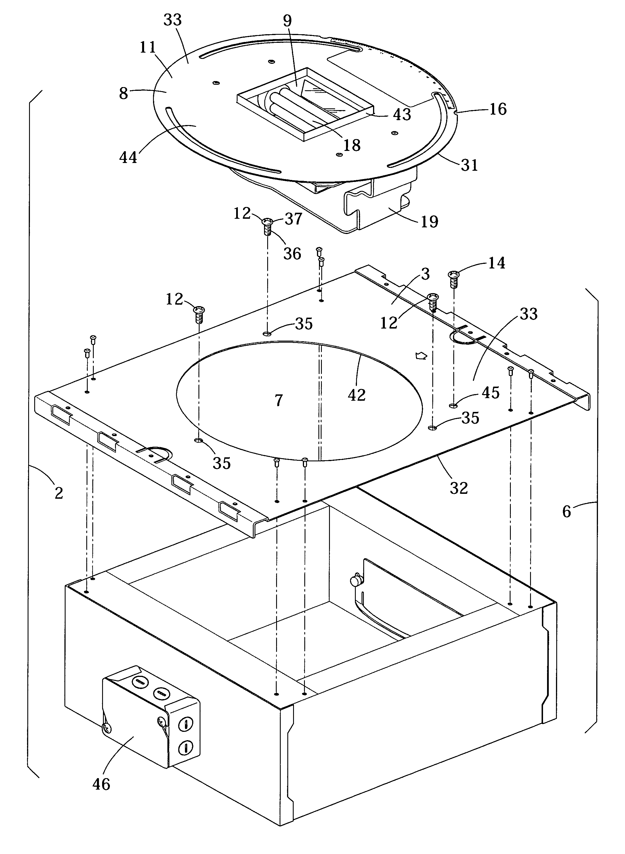
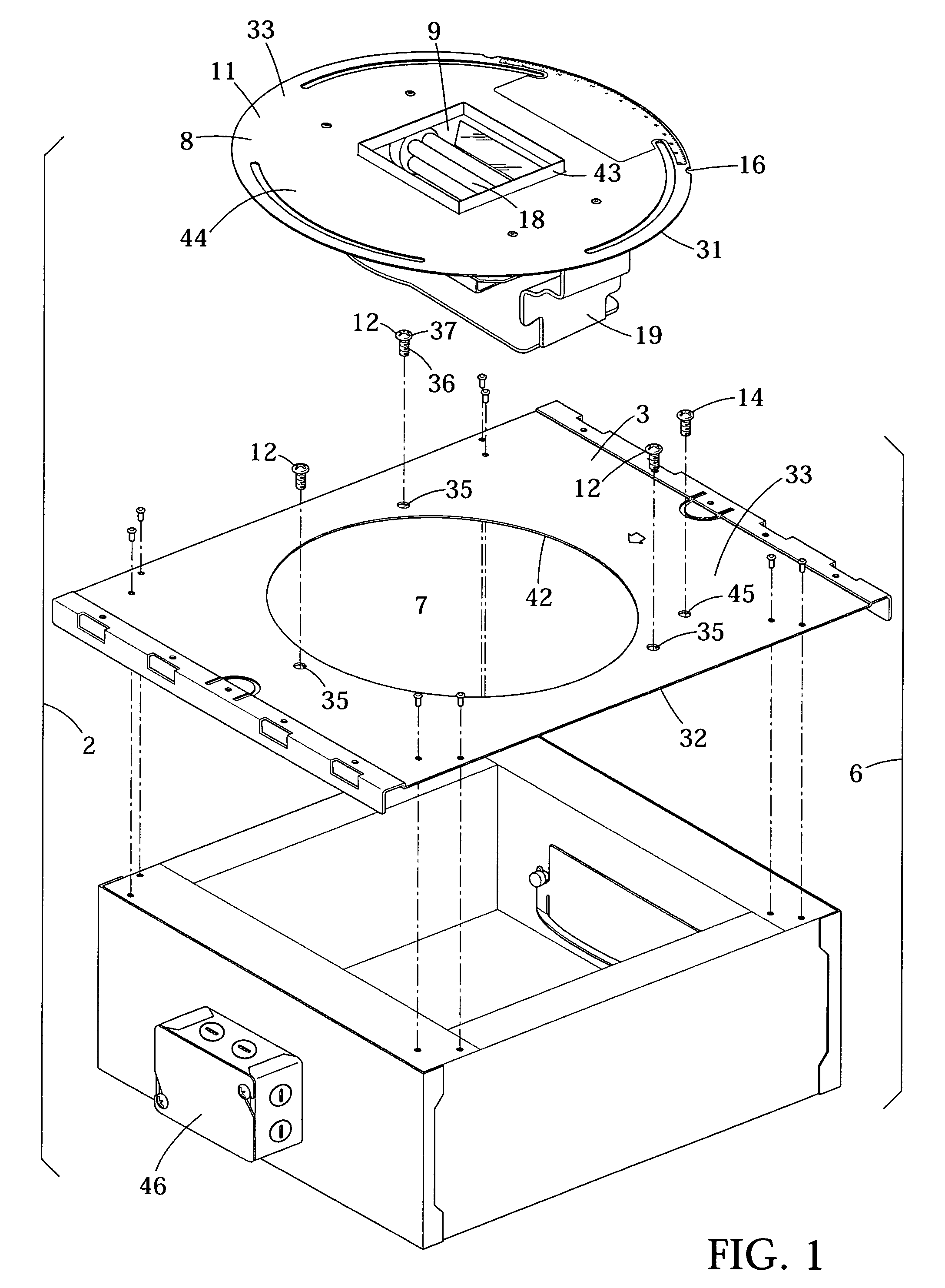
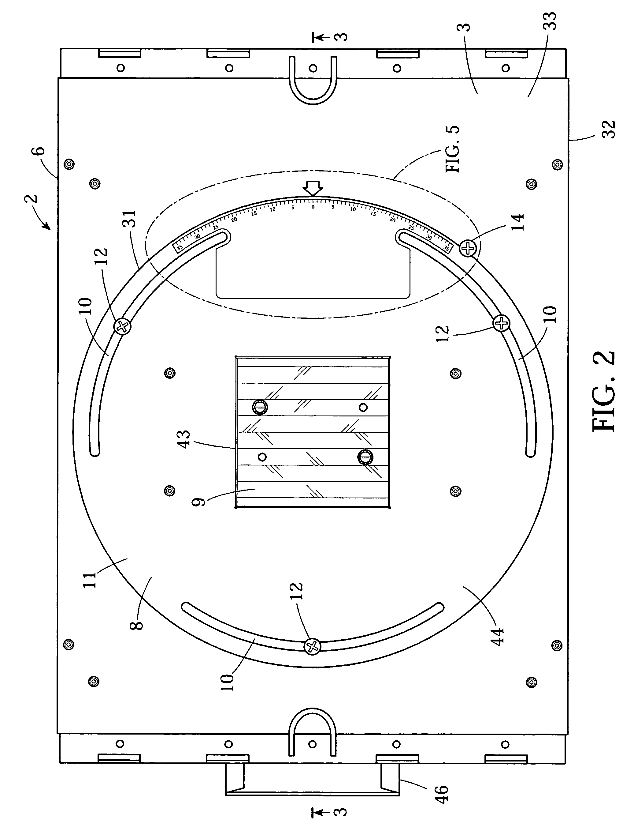
[0027]Referring to FIGS. 1 through 7, the present invention is directed to a recessed light assembly 2, which includes an enclosure 6 having a wall 3 (such as a bottom wall) with an opening 7 therethrough and includes an illumination element 18 disposed within the enclosure 6. The enclosure 6 is preferably formed entirely or primarily of metal (such as sheet metal) and preferably, though not necessarily, is in the form of a box-like structure having six substantially orthogonal sides or walls. Alternatively, the enclosure may have other forms or may consist of a single wall 3 with an opening 7. As depicted, the wall 3 of the enclosure 6 may be separable from the remainder of the enclosure 6.

[0028]The enclosure 6 is fixable to a support structure of a dwelling, such as support studs or other support structure on the surface or within a wall or ceiling. As is typical, it is anticipated that the recessed light assembly 2 will be installed during construction (or re-construction) of the...


PUM


Abstract

A recessed light assembly having an illumination element and having an enclosure attachable to a support structure of a dwelling has a rotating aperture plate rotatably mounted to a wall of the enclosure. The rotating aperture plate has an illumination aperture disposed over an opening in the wall of the enclosure and the recessed light assembly has adjustable fasteners, accessible from an exterior of the recessed light assembly, which adjustable fasteners selectively permit and prevent rotation of the rotating aperture plate relative to the enclosure allowing a user to adjust the rotational alignment of the illumination aperture relative to the enclosure of an installed light assembly without disengaging an attached assembly from the support structure. The illumination element may be fixed relative to the rotating aperture plate or may be fixed relative to the enclosure. The rotating aperture plate and the enclosure may have rotational alignment reference marks and a rotational alignment indicator which serve to indicate a present rotational alignment of the aperture plate relative to the enclosure.

Description

FIELD OF THE INVENTION[0001]The invention pertains to the field of recessed lighting and, in particular, to recessed lighting assemblies.BACKGROUND OF THE INVENTION[0002]Recessed lighting is very popular because it provides light in a subtle, unobtrusive manner providing improved decor. A recessed light assembly typically comprises a box-like enclosure with a fixed illumination aperture located on a wall of the enclosure and with an illumination element affixed inside the enclosure. Other apertures in the enclosure may be present for routing electrical power and control lines or for ventilation. For practical and regulatory reasons, such assemblies are typically constructed primarily of unpainted metal (such as sheet metal) and the enclosure is usually entirely metal. Such assemblies are typically affixed to a support structure within a ceiling or wall in order to provide a secure, concealed attachment.[0003]Illumination apertures of many different sizes and shapes are available to ...

Claims


Application Information

Patent Timeline
Patent Type & Authority Patents(United States)
IPC IPC(8): F21S8/00F21V15/00
CPCF21S8/02F21V21/30
Inventor COGLIANO, FRANK
Owner USAI LLC
Learn More