Supercharge Your Innovation With Domain-Expert AI Agents!

Method for defining a base line

Active Publication Date: 2010-12-28
BISSANTZ NICOLAS
View PDF2 Cites 2 Cited by
  • Summary
  • Abstract
  • Description
  • Claims
  • Application Information

AI Technical Summary

Benefits of technology

This method ensures efficient use of space by selecting the appropriate baseline based on calculated ratios, allowing for accurate representation of data values within the limited space, optimizing the representation of sparklines.

Problems solved by technology

In any case the problem arises where to locate the base line from which the bars representing the sparkline extend.

Method used


Image

  • Method for defining a base line
  • Method for defining a base line
  • Method for defining a base line

Examples


Embodiment Construction

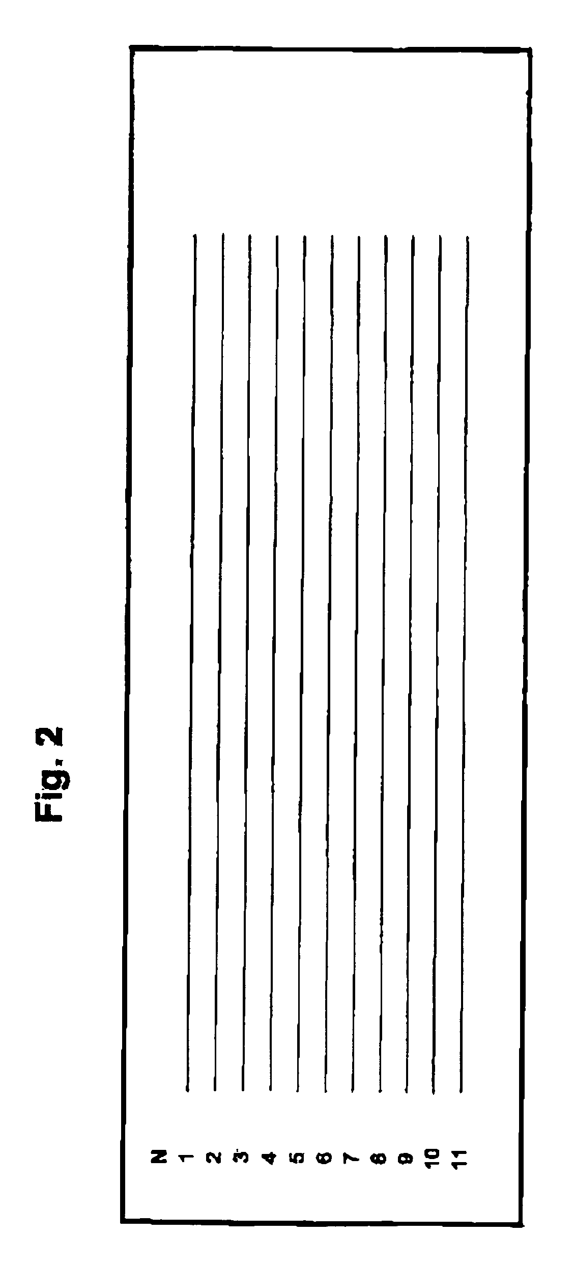
[0046]FIG. 2 shows the first border 1 and the second border 11 of a space which is available for representing a sparkline.

[0047]The first, upper border is assigned the line number 1 and the lower second border is assigned the line number 11. The available space between the lines 1 and 11 is separated by nine additional potential base lines which are assigned the numbers 2-10 as may be evident from FIG. 2.

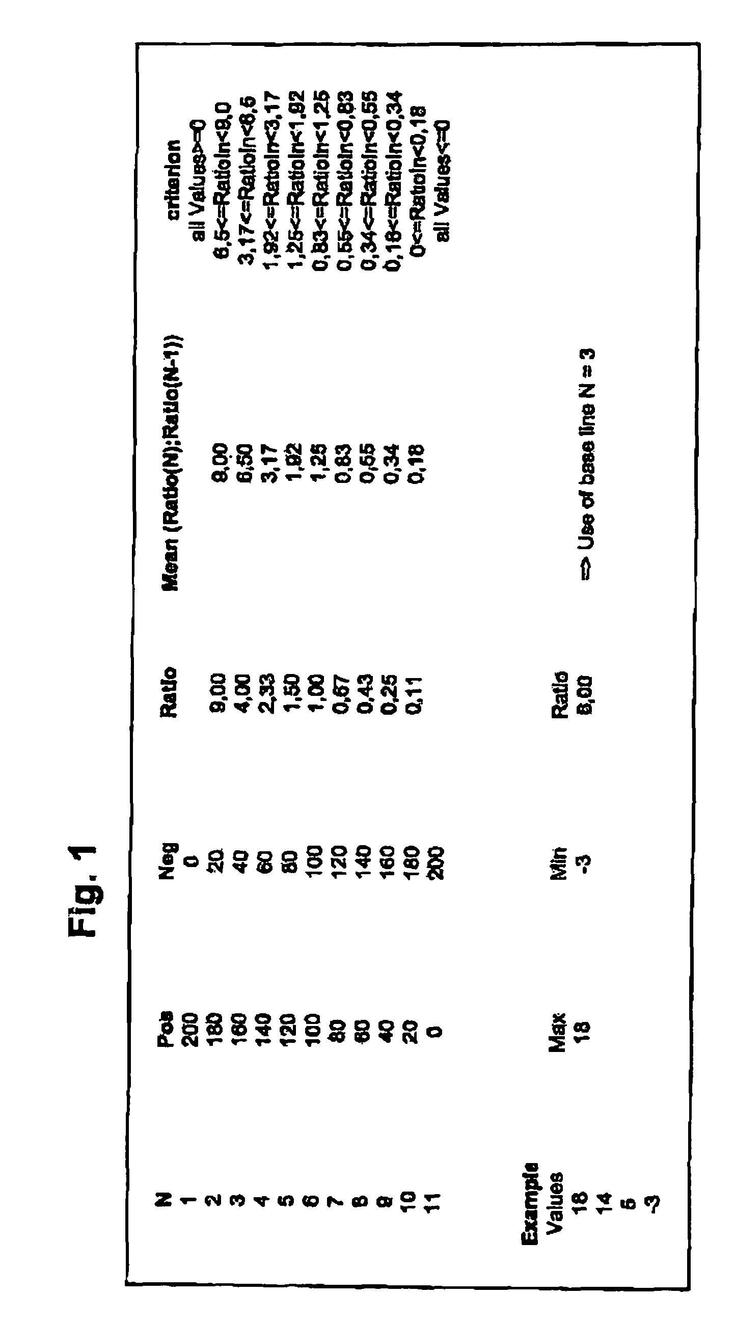
[0048]In addition, each potential base line is assigned a position-value as follows:

[0049]The distance between lines 1 and 11 is assigned the numerical value of for example 200. Of course any other value would also be conceivable. Since the potential base lines separate the available space between the first 1 and the second border 11 lines into 10 equal intervals, each interval corresponds to a numerical value of 20.

[0050]For each of the lines 1-11 or at least for potential base lines 2-10 a pair of values is determined as follows: A first value represents the distance between the r...


PUM


Abstract

The present invention is directed to a method for defining a base line for a sparkline having vertical or horizontal bars representing positive and negative values of a set, with the bars representing negative values extending to one side of the base line and the bars representing positive values extending to the other side of the base line. The diagram is located in a space having two borders.

Description

BACKGROUND OF THE INVENTION[0001]The present invention refers to a method for defining a base line for a sparkline comprising or consisting of vertical or horizontal bars wherein the bars represent positive and negative values of a set of values, wherein the bars representing negative values extend to one side of the base line and the bars representing positive values extend to the other side of the base line and wherein the diagram is located in a space having a first and a second border.[0002]Sparklines are word-sized graphics which may be included into texts or tables and which depict high amounts of data in small spaces. For example, sparklines comprising upward and downward bars indicate current and historical business figures, like revenues or sales, stock quotes or wins and losses for example in soccer, tennis or baseball matches.[0003]The length / height of the bars of the sparkline corresponds to the absolute values of a set of values on which the sparkline is based.[0004]If ...

Claims


Application Information

Patent Timeline
Patent Type & Authority Patents(United States)
IPC IPC(8): G06F17/21
CPCG06F17/241G06F40/169
Inventor BISSANTZ, NICOLAS
Owner BISSANTZ NICOLAS
Features
  • R&D
  • Intellectual Property
  • Life Sciences
  • Materials
  • Tech Scout
  • Unparalleled Data Quality
  • Higher Quality Content
  • 60% Fewer Hallucinations
Learn More