Method and system for multi-layer network routing

a multi-layer network and routing technology, applied in the field of telecommunications network control processing, can solve the problems of unnecessarily complicating route calculation, limitation that unidirectional links must have the same capabilities at both ends, etc., and achieve the effect of facilitating multi-layer routing, eliminating or greatly reducing disadvantages and problems associated

Active Publication Date: 2011-02-15
DR REDDYS LAB LTD +1
View PDF15 Cites 45 Cited by
  • Summary
  • Abstract
  • Description
  • Claims
  • Application Information

AI Technical Summary

Benefits of technology

[0008]From the foregoing, it may be appreciated by those skilled in the art that a need has arisen for a technique to provide link state advertisements in a telecommunications network in order to facilitate multi-layer routing. In accordance with the present invention, a method and system for multi-layer network routing are provided that substantially eliminate or greatly reduce disadvantages and problems associated with conventional route calculation techniques.

Problems solved by technology

This unnecessarily complicates route calculation and adds the limitation that unidirectional links must have the same capabilities at both ends.

Method used


Image

  • Method and system for multi-layer network routing
  • Method and system for multi-layer network routing
  • Method and system for multi-layer network routing

Examples


Embodiment Construction

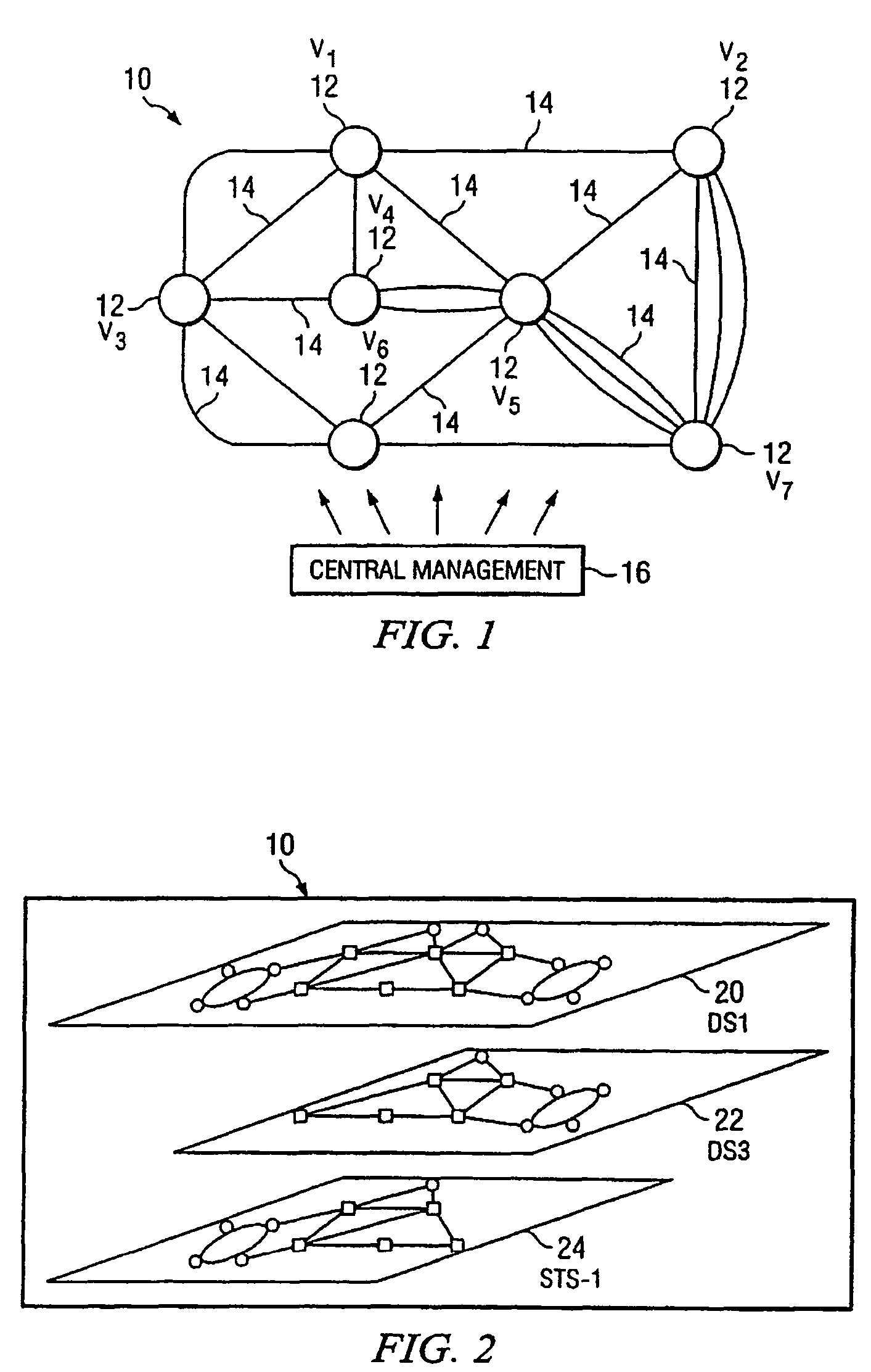
[0029]FIG. 1 is a simplified diagram of a telecommunications network 10. Telecommunications network 10 includes a plurality of switching points or nodes 12 interconnected by links 14. Each node 12 is operable to transfer telecommunications signals using one or more signal types. Examples of signal types include Digital Service Level 1 (DS1), DS3, Virtual Tributary Level 1.5 (VT1.5), Synchronous Transport Signal Level 1 (STS-1), STS-3c, and Optical Carrier Level 3 (OC-3). Nodes 12 may also support other conventional signal types readily known by those skilled in the art. Each signal type represents a different connection routing layer within telecommunications network 10. For each signal carried within telecommunications network 10, a route to its intended destination is determined. Determination of the route through telecommunications network 10 may be made at an originating node 12, a node 12 acting as a supervisory or control node, or at a centralized management node 16 according ...


PUM


Abstract

Each node of a telecommunications network determines interface point connection type attributes available for each signal type supported by the node. Each signal type represents a different connection routing layer within the telecommunications network. Adaptation costs involved in traversing from one connection routing layer to another connection routing layer in the node are calculated. The connection type attributes and adaptation costs are included in a link state advertisement broadcasted by each node in the telecommunications network. A route calculation is performed for a desired signal to determine a route through the telecommunications network for the signal. The route calculation takes into account the various connection type attributes, availability, and adaptation costs in determining the shortest route for the signal through the telecommunications network.

Description

CROSS REFERENCE TO RELATED APPLICATIONS[0001]This Application claims the benefit of U.S. Provisional Application No. 60 / 661,203, filed Mar. 11, 2005.[0002]This Application is a continuation-in-part application of U.S. application Ser. No. 10 / 355,306, filed Jan. 31, 2003, now U.S. Pat. No. 7,301,911.TECHNICAL FIELD OF THE INVENTION[0003]The present invention relates in general to telecommunications network control processing and more particularly to a method and system for multi-layer network routing.BACKGROUND OF THE INVENTION[0004]Calculation of a route through a network is based on link attributes advertised by each node in the network. There are several known link attributes that may be advertised by nodes 12 within telecommunications network 10. These link attributes include traffic engineering metric, maximum or total reservable bandwidth, unreserved bandwidth, resource class / color, link protection type, and shared risk link group. The traffic engineering metric specifies the l...

Claims


Application Information

Patent Timeline
Patent Type & Authority Patents(United States)
IPC IPC(8): H04L12/28G06F15/173
CPCH04L45/12H04L45/64H04L45/00
Inventor MACK-CRANE, T. BENJAMINSADLER, JONATHAN B.
Owner DR REDDYS LAB LTD
Why Eureka
Try Eureka