System and method for communicating in a loadbalancing environment

a communication system and loadbalancing technology, applied in the field of communication, can solve the problems of reducing the number of central processing unit (cpu) cycles and requiring additional work, and achieve the effects of reducing the burden on the loadbalancing machine, eliminating or greatly reducing the disadvantages and problems associated, and facilitating the communication session

Active Publication Date: 2005-08-25
CISCO TECH INC
View PDF55 Cites 41 Cited by
  • Summary
  • Abstract
  • Description
  • Claims
  • Application Information

AI Technical Summary

Benefits of technology

[0004] From the foregoing, it may be appreciated by those skilled in the art that a need has arisen for an improved communications approach that provides for a reduction in the burden on a loadbalancer associated with communications between two endpoints. In accordance with one embodiment of the present invention, a system and method for establishing a network communication in a loadbalancing environment are provided that substantially eliminate or greatly reduce disadvantages and problems associated with conventional loadbalancing techniques.
[0005] According to one embodiment of the present invention, there is provided a method for communicating in a loadbalancing environment that includes receiving a request packet from a network access server (NAS) to initiate a communication session. The request packet is then communicated to a tunneling protocol network server (TPNS) and a response packet is received in response to the request packet. The response packet establishes a tunnel that facilitates the communication session and that includes an identification element associated with the TPNS such that a data transfer associated with the communication session is executed between the NAS and the TPNS.
[0006] Certain embodiments of the present invention may provide a number of technical advantages. For example, according to one embodiment of the present invention a communications approach is provided that allows a loadbalancer to only be actively involved in the initiation of a communication session. This reduction in responsibility for the loadbalancer operates to increase throughput as two points or nodes communicate more directly instead of having to direct all information through the loadbalancer for processing. This may further reduce the number of central processing unit (CPU) cycles, which may be intensive and require additional work to be performed by the loadbalancer. Accordingly, the loadbalancer may be relegated to simple information transfer or packet switching (generally not involving a modification of address information). The removal of the loadbalancer from the data transfer interaction between two nodes may further alleviate responsibilities designated for the loadbalancer such that more robust network traffic may be accommodated in the network.
[0007] Yet another technical advantage of one embodiment of the present invention is also a result of the removal of the loadbalancer from data transfer traffic. The decreased reliance on the loadbalancer operates to better allocate memory resources because information per-tunnel state is no longer maintained by the loadbalancer. In addition, the decreased dependency on the loadbalancer allows for improved failover characteristics whereby, if the loadbalancer would become dysfunctional or non-operational, associated communications sessions would not be lost. The continued operation of existing communication tunnels may be preserved in accordance with the teachings of the present invention by relegating the loadbalancer to tasks involving only the initiation of the communications session. Embodiments of the present invention may enjoy some, all, or none of these advantages. Other technical advantages may be readily apparent to one skilled in the art from the following figures, description, and claims.

Problems solved by technology

This may further reduce the number of central processing unit (CPU) cycles, which may be intensive and require additional work to be performed by the loadbalancer.

Method used


Image

  • System and method for communicating in a loadbalancing environment
  • System and method for communicating in a loadbalancing environment
  • System and method for communicating in a loadbalancing environment

Examples


Embodiment Construction

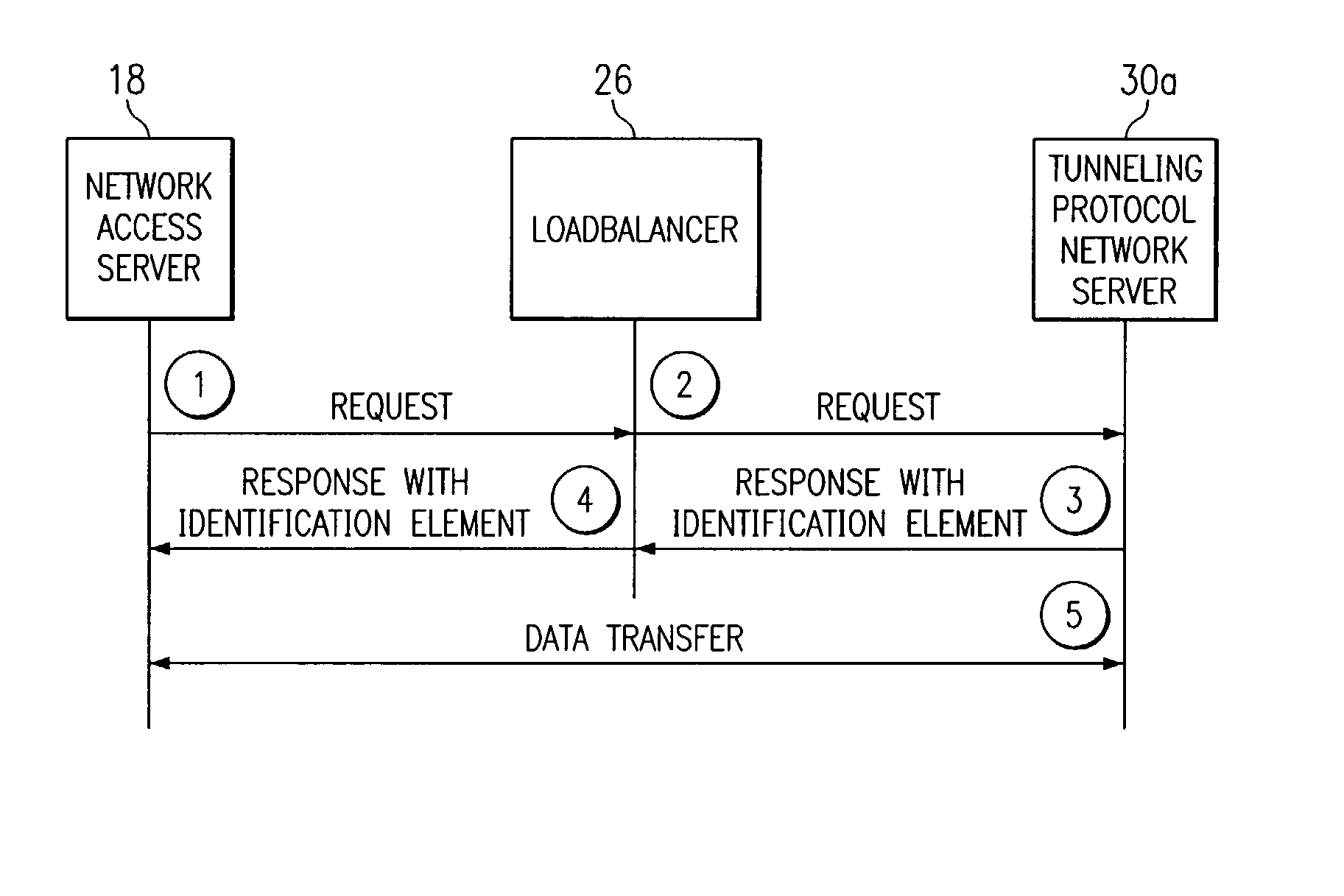
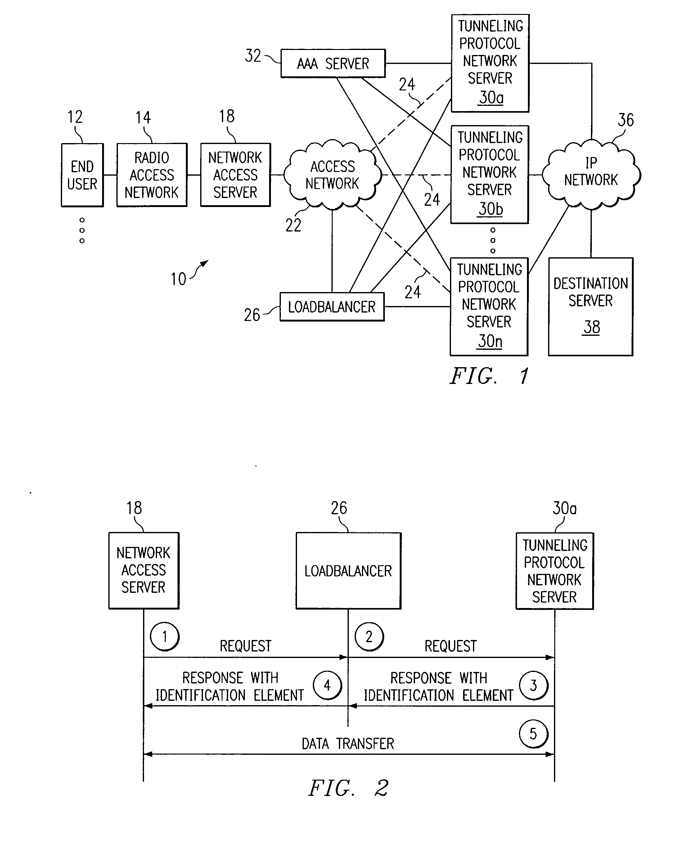
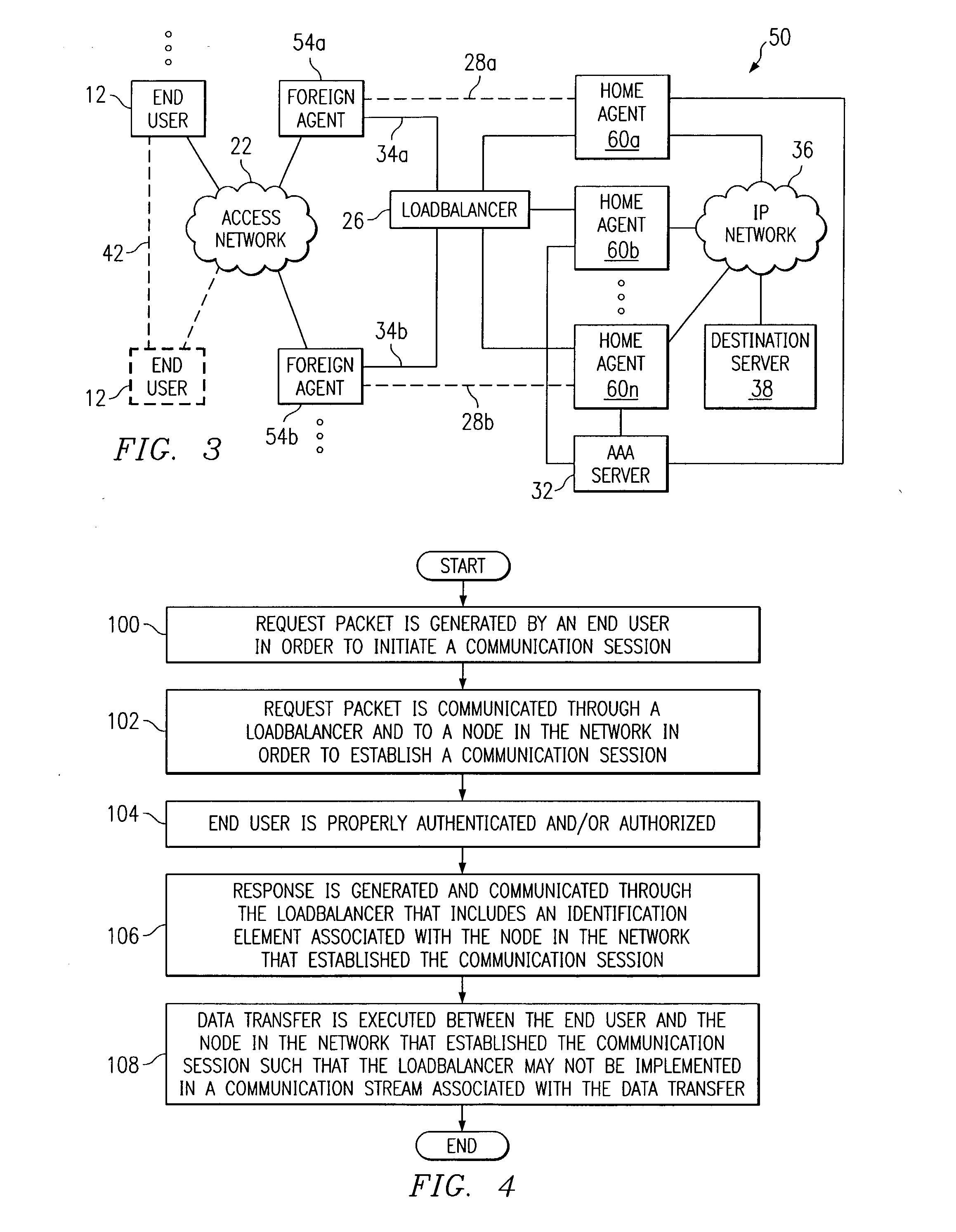
[0013]FIG. 1 is a simplified block diagram illustrating a communication system 10 for communicating data in a loadbalancing environment. Communication system 10 includes an end user 12, a radio access network (RAN) 14, a network access server (NAS) 18, and an access network 22. Additionally, communication system 10 includes a loadbalancer 26, multiple tunneling protocol network servers (TPNSs) 30a-n, an authentication, authorization, and accounting (AAA) server 32, an internet protocol (IP) network 36, and a destination server 38.

[0014] In accordance with the teachings of the present invention, communication system 10 operates to alleviate the responsibilities associated with loadbalancer 26 in providing optimal communications between end user 12 and IP network 36. Two stages generally exist in communications flows that involve end user 12. A first stage relates generally to initiation whereby a communication session may be prompted by end user 12. A second stage relates generally ...


PUM


Abstract

A method for communicating in a loadbalancing environment is provided that in a particular embodiment includes receiving a request packet from a network access server (NAS) to initiate a communication session. The request packet is then communicated to a tunneling protocol network server (TPNS) and a response packet is received in response to the request packet. The response packet establishes a tunnel that facilitates the communication session and that includes an identification element associated with the TPNS such that a data transfer associated with the communication session is executed between the NAS and the TPNS.

Description

TECHNICAL FIELD OF THE INVENTION [0001] This invention relates in general to communications and more particularly to system and method for communicating in a loadbalancing environment. BACKGROUND OF THE INVENTION [0002] Networking architectures are growing increasingly complex in communications environments. In addition, the augmentation of clients or end users wishing to communicate in a network environment have caused many networking architectures and systems to respond by adding elements to accommodate the increase in network traffic. Communication tunnels may be used in order to establish or to gain access to a network, whereby an end user or a client may initiate the corresponding tunneling protocol by invoking a central location or a single network node. Such central locations may be obligated to execute an excessive number of tasks that overburden or overtax the central location. [0003] In addition, the unreasonable delegation of a disproportionate number of duties may decrea...

Claims


Application Information

Patent Timeline
Patent Type & Authority Applications(United States)
IPC IPC(8): H04L12/28H04L12/46
CPCH04L12/4633H04L12/2859
Inventor O'ROURKE, CHRISBATZ, ROBERT M.DABBOUSSI, RABIH A.GLOTZER, JOHN M.MENDITTO, LOUIS F.PATEL, ALPESH S.LEUNG, KENT K.
Owner CISCO TECH INC
Why Eureka
Try Eureka