

Catching machine
a technology of catching machine and ball, which is applied in the field of catching machine, can solve the problems of not returning the ball and the ball cannot be returned to an arbitrary position
- Summary
- Abstract
- Description
- Claims
- Application Information
AI Technical Summary
Problems solved by technology
Method used
Image

Examples
Embodiment Construction
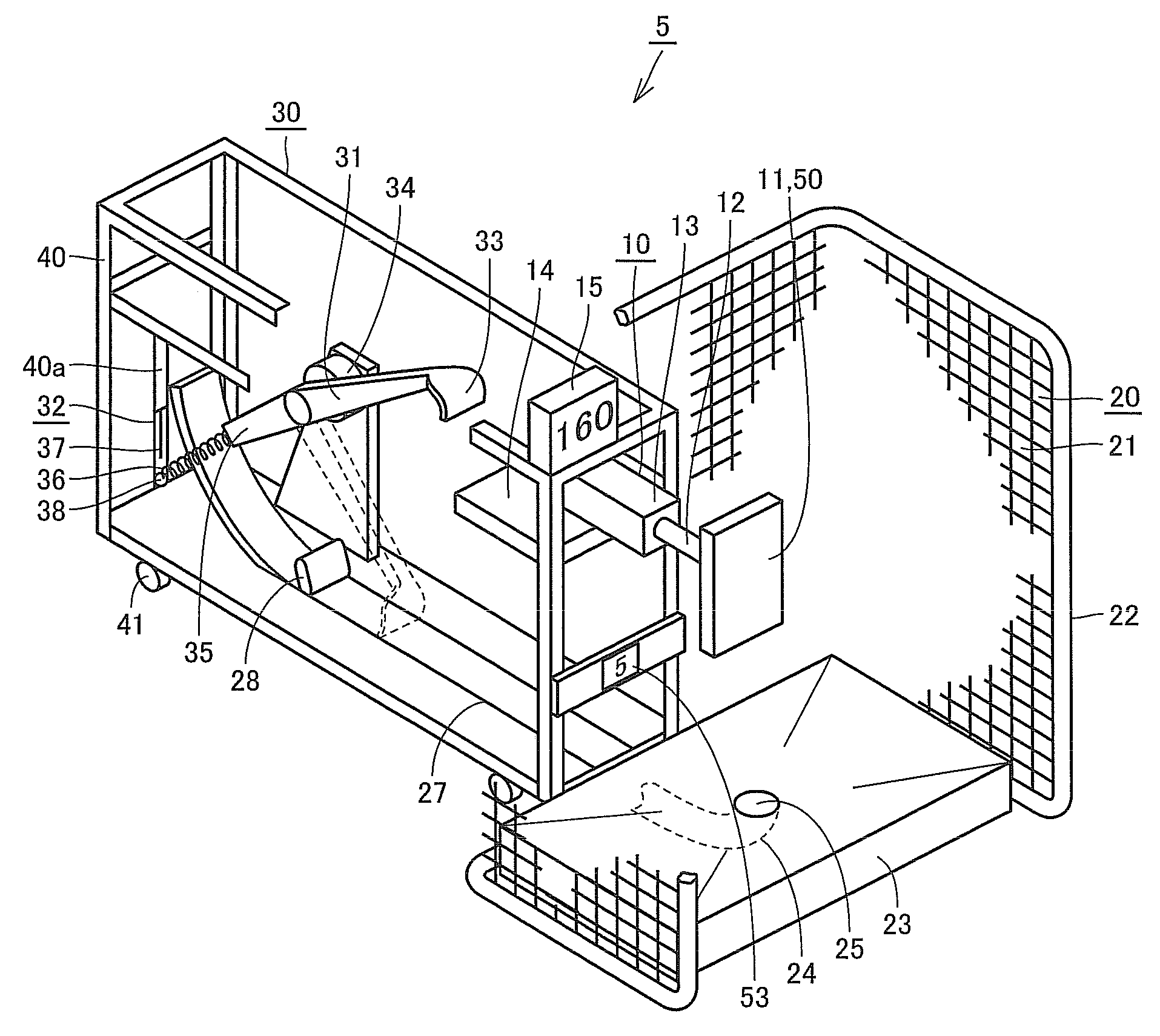
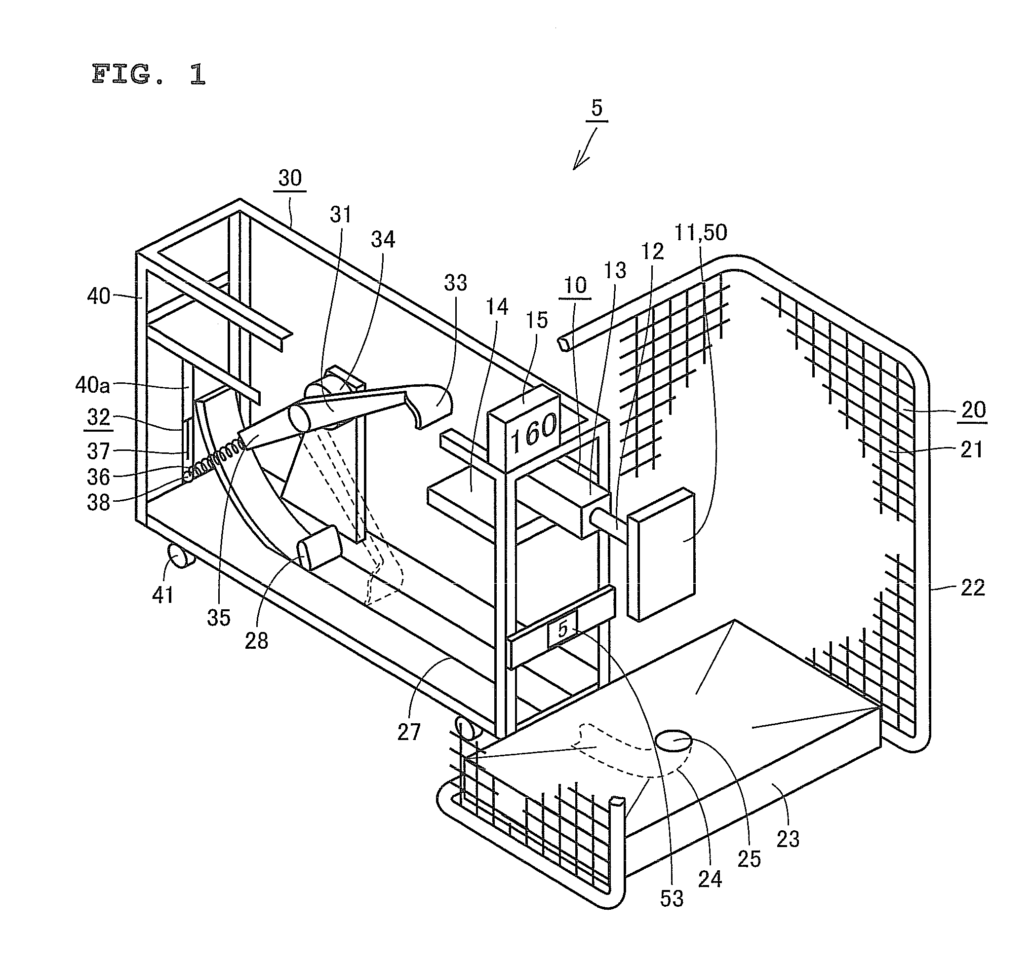
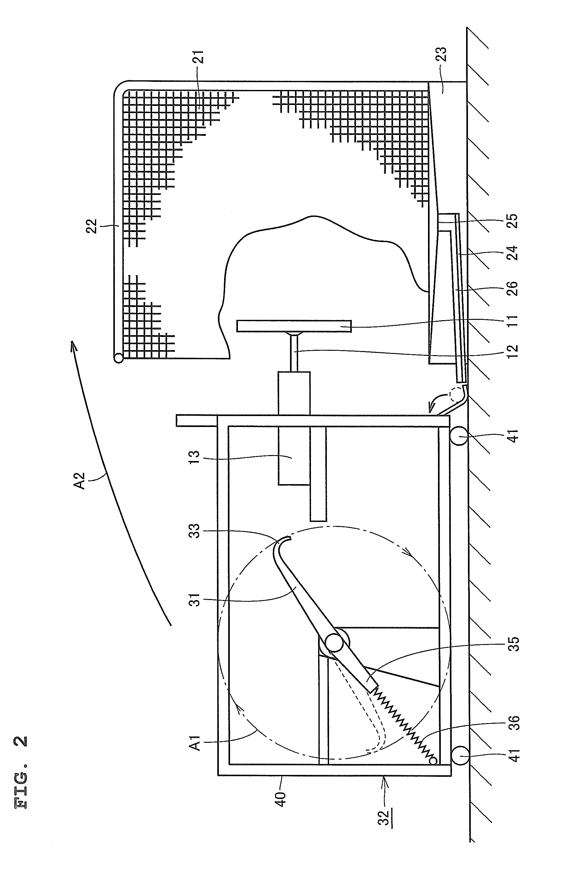
[0023]Hereinafter, an embodiment of the present invention will be described with reference to the accompanying drawings. FIG. 1 is a perspective view showing an overall structure of a catching machine according to the present invention. FIG. 2 is a side view of the catching machine when viewed from a lateral direction. Referring to FIGS. 1 and 2, a catching machine 5 includes a target portion 10 having a target 11 that serves as a pitching target for a pitcher, a ball collecting portion 20 corresponding to catching means, for collecting a ball hitting the target portion 10, and a ball returning portion 30 corresponding to ball returning means, for returning a ball collected by the ball collecting portion 20 to the pitcher. The target portion 10 and the ball collecting portion 20 are provided on a frame 40.
[0024]The target portion 10 includes the target 11 and a detecting portion 13 supporting the target 11 by a shaft 12 for detecting the speed of a ball hitting the target 11. The de...
PUM
 Abstract
Description
Claims
Application Information