Visible light communication apparatus and visible light communication method

a technology of communication apparatus and visible light, which is applied in the direction of satellite communication transmission, transmission, transmission, etc., can solve the problems of limited number of states that a spot-display device can display, difficult to display a detailed state, and difficult to display all the states of device types and contents

Inactive Publication Date: 2011-03-22
PANASONIC CORP
View PDF21 Cites 103 Cited by
  • Summary
  • Abstract
  • Description
  • Claims
  • Application Information

AI Technical Summary

Benefits of technology

[0013]The visible light communication apparatus is capable of outputting detailed information regarding operation states without a large display. The visible light communication apparatus further allows easy and detailed recognition of an operation state of the visible light communication apparatus by receiving, at a receiver, visible light emitted from the visible light communication apparatus without a large display, which includes a receiving unit and a display.
[0015]The present embodiment can provide the visible light communication apparatus and the visible light communication method that are capable of outputting detailed information regarding operation states without a large display.

Problems solved by technology

However, there is a limit to the number of states that a spot-display device can display, and it is usually difficult to display a detailed state.
Further, since it is necessary to provide different spot-display devices for displaying various items in accordance with the device types and contents to be displayed (e.g., operation / non-operation of an electric appliance, states of device components, states of connected devices), it is difficult to display all the states of device types and contents when there is a physical limit to areas where spot-display devices can be installed.
Moreover, users may have a hard time understanding display contents since various states are specified by continuous lightings, lights-out, blinks, etc.
However, some electric appliances are difficult to install such panel display devices due to physical and limitations.
Further, in some cases, depending on where such electrical appliances are installed, it may be hard for users to view the panel display devices on those appliances directly, thereby hindering users' recognition of the displayed contents themselves.
Therefore, such a communication apparatus is not capable of displaying detailed states including whether the communication apparatus is being connected or not, a state of a connected communication apparatus, and a state of a transmission line.

Method used


Image

  • Visible light communication apparatus and visible light communication method
  • Visible light communication apparatus and visible light communication method
  • Visible light communication apparatus and visible light communication method

Examples


Embodiment Construction

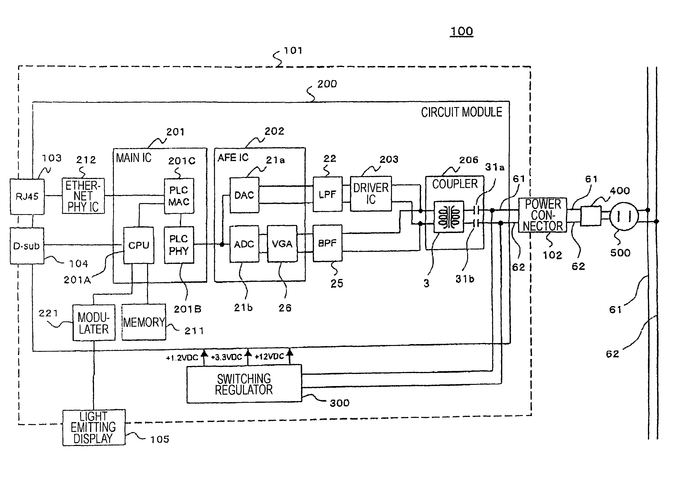
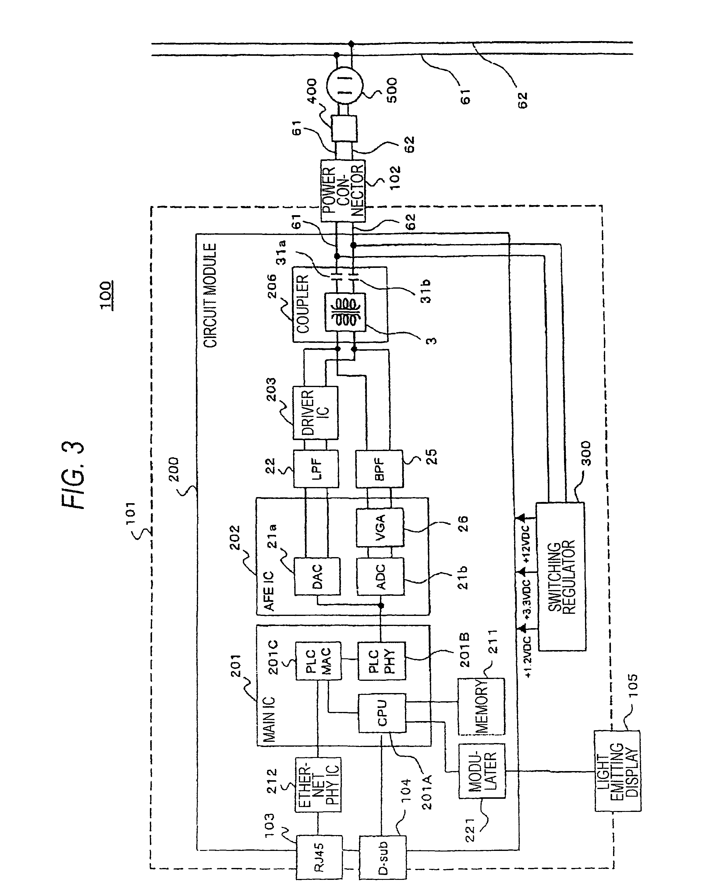
[0028]The present embodiment is described in the following with reference to the drawings, using as an example a PLC modem, which is a communication apparatus that performs power line communication.

[0029]The PLC modem according to the present embodiment performs communication using, for instance, an OFDM (Orthogonal Frequency Division Multiplexing) method in which a plurality of sub-carriers are transmitted.

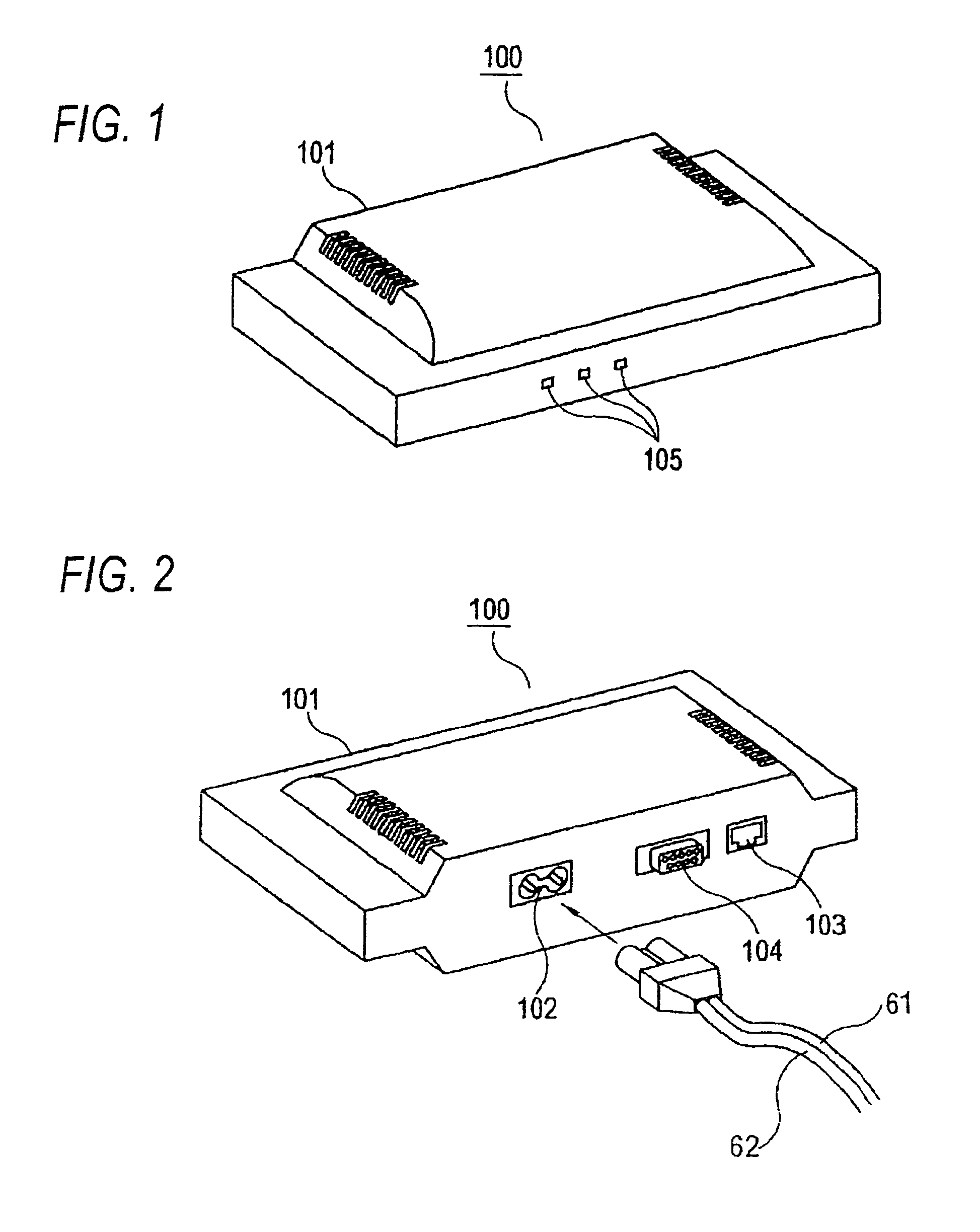
[0030]PLC modem 100 is an example of the visible light communication apparatus and includes chassis 101. As shown in FIG. 1, light emitting portion 105 utilizing such luminous bodies as LEDs (Light Emitting Diodes) is provided on the front side of chassis 100. Light emitting portion 105, which indicates an operation state of PLC modem 100, includes three parts for emitting visible light as shown in FIG. 1. Although the number of parts of this portion can be set arbitrarily, a luminous body is provided at least in one part to enable high-speed flashing. Visible light is defined he...


PUM


Abstract

A PLC modem performs communication via transmission lines made of a pair of cables as an example of a wired transmission line. Data displaying an operation state of the PLC modem is transmitted to a light emitting part via a modulator, and is converted into a high-speed flash signal for output.

Description

INCORPORATION BY REFERENCE[0001]This application is related to the following patent application which is hereby incorporated by reference in its entirely: US 2006 / 0056855 A1, ILLUMINATIVE LIGHT COMMUNICATION DEVICE, Inventors: Masao Nakagawa et al., filed on Oct. 23, 2003.BACKGROUND[0002]1. Field of the Invention[0003]The present invention relates to a visible light communication apparatus that performs visible light communication by using a modulation signal for changing an emitting state of visible light, and a visible light communication method that outputs an operation state of an electric appliance.[0004]2. Description of Related Art[0005]When displaying states of various electric appliances including a communication apparatus, various devices are used including a basic spot-like display such as an LED or a lamp (hereinafter referred to as a “spot-display device”) and a 2D-display device such as a CRT display and an LCD (hereinafter referred to as a “panel display device”).[000...

Claims


Application Information

Patent Timeline
Patent Type & Authority Patents(United States)
IPC IPC(8): H04B10/00H04B10/08H04B3/54H04B10/07H04B10/11H04B10/116H04B10/118H04B10/524
CPCH04B10/1141H04B10/116
Inventor KOGA, HISAO
Owner PANASONIC CORP
Why Eureka
Try Eureka