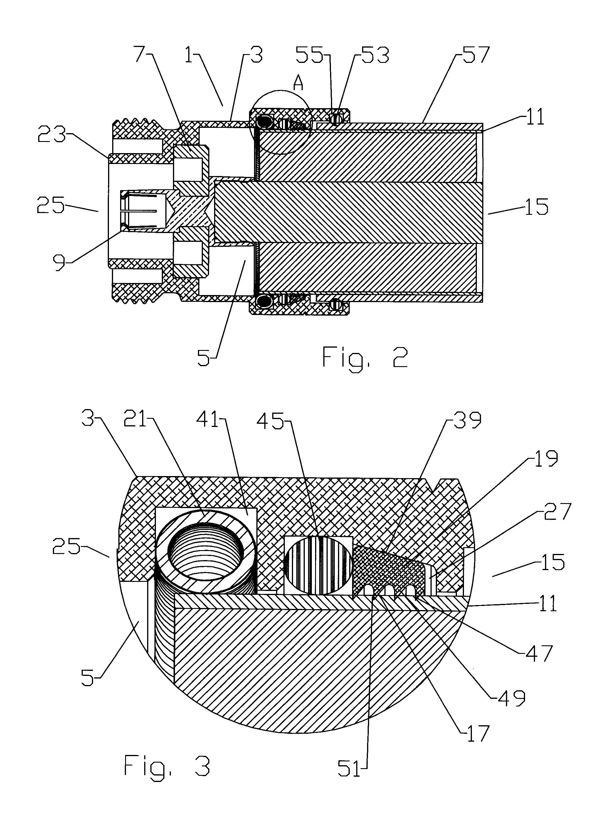
[0054]Clamp ring threads 37 between the connector body bore 5 and an outer diameter of the clamp ring 31 may also be provided as an alternative to the retaining feature 29. To enable the coaxial connector 1 to be supplied as a ready for installation assembly, the clamp ring threads 37 may be combined with the snap groove 33 and snap 35 interconnection to provide an assembly that may be supplied with the clamp ring 31 already attached to the connector body 3, preventing disassembly and / or loss of the internal elements, as shown for example in FIGS. 7-14. Where the retaining feature 29 combines the clamp ring threads 37 with the snap groove 33 and snap barb 35, the longitudinal travel of the clamp ring 31 with respect to the connector body 3 via threading along the clamp ring threads 37 is limited by a width within the snap groove 33 across which the snap barb 35 may move before interfering with the snap groove 33 sidewalls.
[0071]When formed as helical grooves or barbs the jacket grip 71 may be threaded upon the jacket 57, providing assembly assistance to progressively move the outer conductor 11 under and past the spring contact 21 as the jacket grip 71 is threaded onto the jacket 57. The threading also assists with connector 1 to coaxial cable 13 retention.
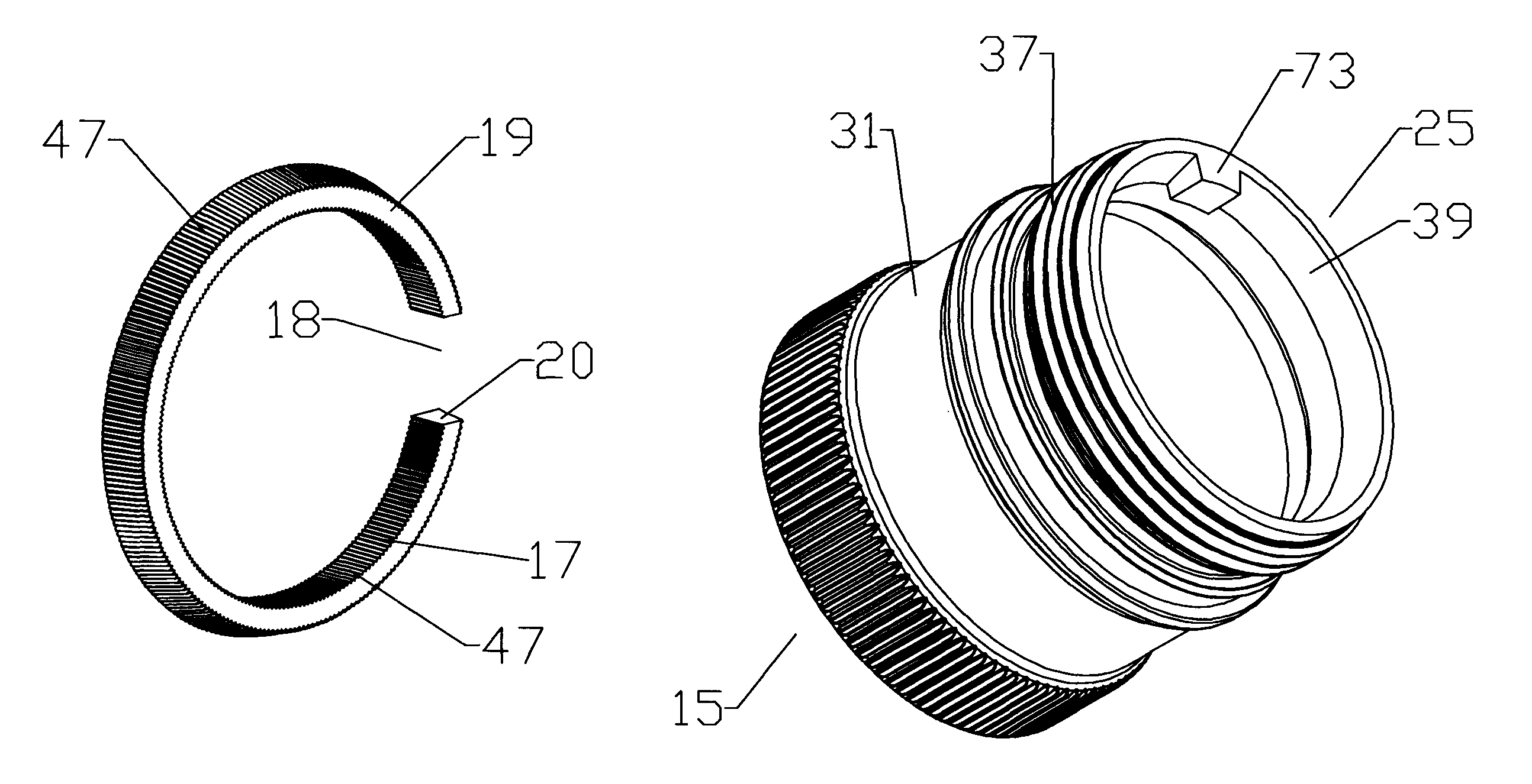
[0073]One skilled in the art will appreciate that anti-rotation characteristics and the corresponding strengthening of the resulting interconnection between the coaxial cable 13 and the coaxial connector 1 is also desirable when applied to conventional coaxial connector configurations, such as outer conductor leading edge clamp type coaxial connectors, for example as shown in FIG. 35. As coaxial cable configurations with reduced thickness and / or other strength characteristic outer conductors are developed to reduce weight and / or reduce material costs, the conventional circumferential clamp interconnection retaining the coaxial connector upon the coaxial cable becomes weaker. To distribute the interconnection stresses and / or provide reinforcement that both stabilizes the coaxial connector axially and / or alternatively benefits from material strength contributions to the coaxial cable 13 by the jacket 57, a grip ring 19 arrangement may be applied to progressively grip the outer conductor 11 and / or jacket 57 as the clamp ring 31 is tightened. The grip ring 19 being driven against a wedge surface spacer 75 provided with a wedge surface 39 that clamps the leading edge of the outer conductor 11 against the connector body 3.
[0075]Conversely, once spread, the bias of the grip ring 19 inward towards its relaxed state creates a gripping engagement between the grip surface 17 and the outer diameter surface of the outer conductor 11 or jacket 57. If tension is applied between the connector body 3 and the coaxial cable 13 to pull the outer conductor 11 and / or jacket 57 towards the cable end 15, the grip ring 19, engaged via the grip surface 17, is driven against the tapered wedge surface 39, progressively decreasing the depth of the grip ring groove 27, thereby driving the grip ring 19 radially inward and further increasing the gripping engagement as the respective grip surface 17 is driven into the outer diameter surface of the outer conductor 11 or jacket 57. A cable end 15 grip ring groove 27 sidewall may be dimensioned to be at a position where the grip ring 19 diameter relative to the outer conductor 11 diameter is configured for the grip surface 17 to have securely engaged the outer conductor 11 or jacket 57 but which is short of the respective grip ring 19 radial inward movement which may otherwise cause the outer conductor 11 to collapse radially inward and / or unacceptably compress the jacket 57.
[0076]During coaxial cable 13 interconnection with embodiments including a clamp ring 31 and a retaining feature 29 including the clamp ring threads 37, for example as shown in FIGS. 14 and 34, the limited longitudinal movement obtained by threading the clamp ring 31 into the connector body 3 is operative to drive the respective wedge surface 39 against the respective grip ring 19 to move the grip ring 19 radially inward into secure gripping engagement with the outer conductor 11 and / or jacket 57, without requiring the application of tension between the connector body 3 and the coaxial cable 13. Further, in embodiments where the spring contact 21 is also present in the grip ring groove 27, the threading of the clamp ring 31 into the connector body bore 5 may be configured to apply direct and / or via a spacer 43, if present, pressure on the spring contact 21 whereby the spring contact 21 deforms radially inward towards the outer conductor 11, increasing the contact pressure between the spring contact 21 and the outer conductor 11, thereby improving the electrical coupling therebetween.
[0079]One skilled in the art will appreciate the significant manufacturing and installation benefits of the present invention. During manufacturing, a complete coaxial connector 1 assembly ready for installation is prepared with a minimal total number of required elements. If a clamp ring 31 is included in the configuration, the installation of the spring contact 21, spacer 43, grip ring 19 and / or outer conductor seal 45 is simplified by the improved access to the grip ring groove 27, that may then be easily closed by snapping / threading the clamp ring 31 in place after the desired sub elements have been seated in the open end(s) of the connector body bore 5 and / or clamp ring 31. Further, the various environmental seals (outer conductor seal 45, jacket seal 53 and or clamp ring seal 59) may be each overmolded upon the respective groove(s) to provide a single assembly with integral environmental seals. Hole(s) 62 may be formed from the outer diameter to the inner diameter of the clamp ring 31, enabling the outer conductor seal 45 and clamp ring seal 59 to overmolded as a unitary inter-supporting gasket, best shown in FIG. 14. The additional retention of the outer conductor seal 45 provided by overmolding through the hole(s) 62 also enables an outer conductor seal 45 profile with a wiper extension 65. The wiper extension 65 enables the outer conductor seal 45 to more securely seal against both smooth and corrugated outer conductor coaxial cable(s) 13. A clamp ring grip 63, for example as shown in FIG. 31, may be applied to an outer diameter of the clamp ring 31 for improved installer grip during hand threading of the clamp ring 31 into the connector body 3.

