Tire inflation system with integrated wheel seal

a technology of tire inflation and wheel seal, which is applied in the direction of tire measurement, transportation and packaging, vehicle components, etc., can solve the problems of significant portion of the air hose exposed to potentially damaging contact from rocks and debris, and the routing configuration occupies a significant amount of packaging spa

Active Publication Date: 2011-04-26
ARVINMERITOR TECH
View PDF20 Cites 88 Cited by
  • Summary
  • Abstract
  • Description
  • Claims
  • Application Information

AI Technical Summary

Problems solved by technology

Drive axles present challenges for routing air from the air tanks to the tires.
Such a routing configuration takes up a significant amount of packaging space that could otherwise be used for other vehicle components.
Further, due to the external mounting, a significant portion of the air hoses is exposed to potentially damaging contact from rocks, debris, etc.

Method used


Image

  • Tire inflation system with integrated wheel seal
  • Tire inflation system with integrated wheel seal
  • Tire inflation system with integrated wheel seal

Examples


Embodiment Construction

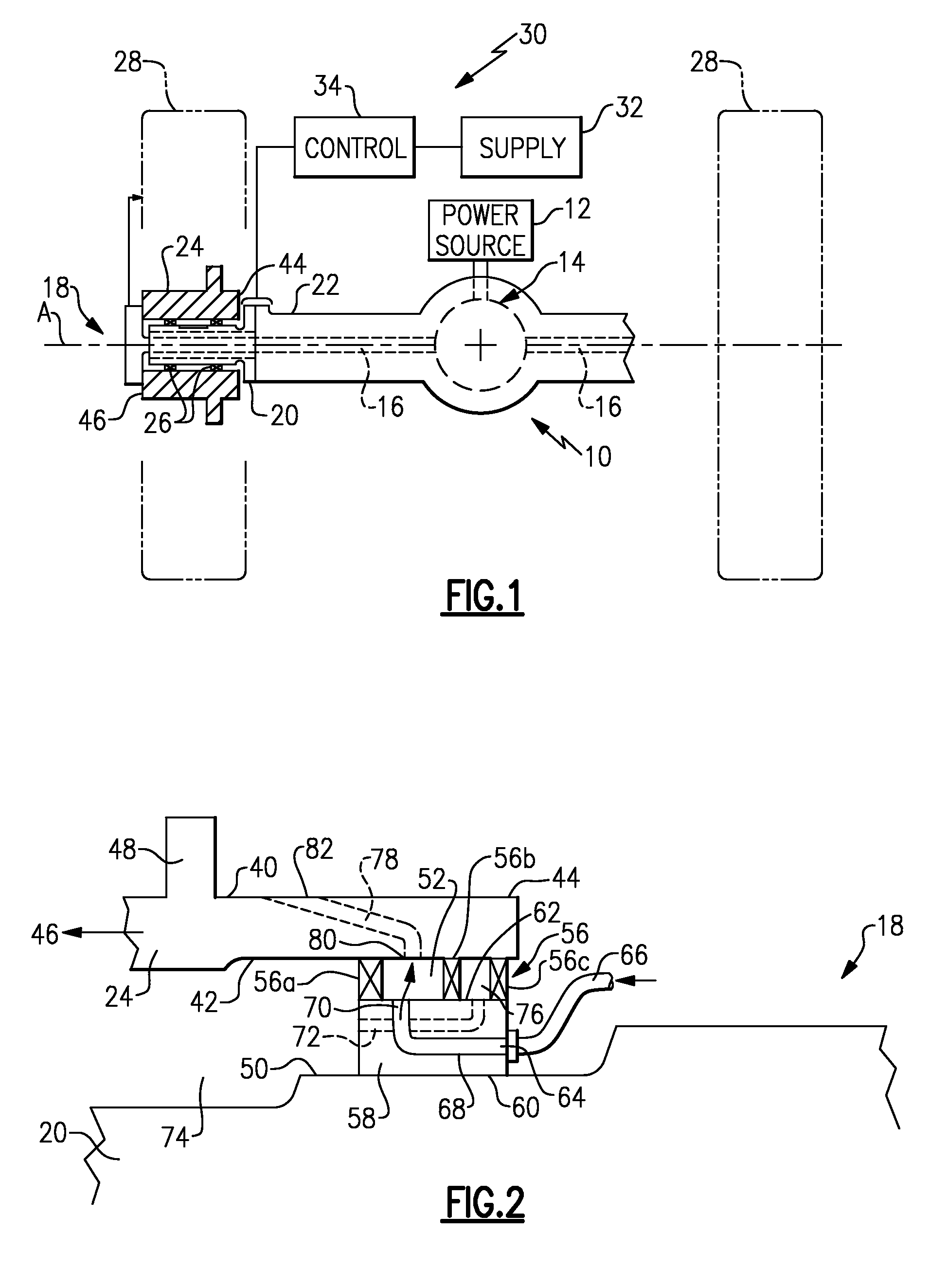
[0016]FIG. 1 shows a drive axle 10 receiving driving input from a power source 12, such as an engine or electric motor for example. The driving input drives an input gear assembly 14 that includes a differential mechanism as known. The gear assembly 14 drives axle shafts 16 that are coupled to drive wheel end assemblies 18. One example of a wheel end assembly 18 is shown to the left of FIG. 1. It should be understood that the opposite wheel end assembly 18 would be similarly configured.

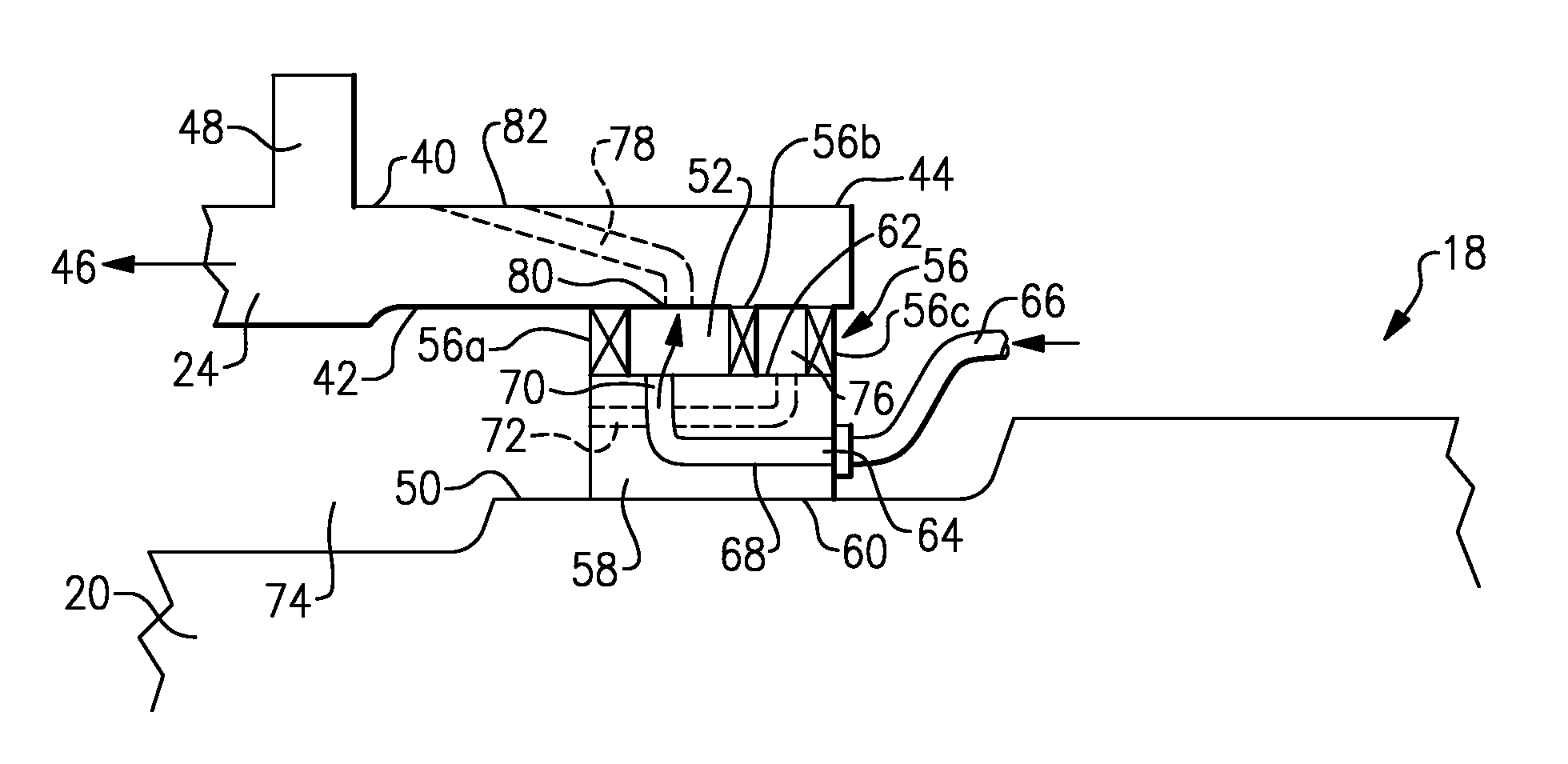
[0017]The wheel end assembly 18 includes a non-rotating spindle 20 that is mounted to an axle housing 22. The axle housing 22 houses the gear assembly 14 and axle shafts 16. A wheel hub 24 is rotatably supported on the spindle 20 by bearings 26. A tire 28 and associated rim are mounted for rotation with the wheel hub 24 about an axis A.

[0018]A tire inflation system 30 includes an air supply reservoir or tank 32 that is used to supply air to the tires 28 when the tires 28 become under-inflated. The tir...


PUM


Abstract

An axle assembly includes a non-rotating component and a wheel hub supported for rotation relative to the non-rotating component about an axis. The wheel hub includes a hub air passage that has a hub inlet and a hub outlet to be fluidly connected to at least one tire. An air chamber is formed at least in part between the non-rotating component and the wheel hub. The air chamber receives air flow from an air source and directs air flow into the hub inlet. A seal assembly engages the wheel hub to seal the air chamber.

Description

TECHNICAL FIELD[0001]The subject invention relates to an axle that includes an air passage that forms part of a tire inflation system. More specifically, the air passage is formed at least in part between a rotating wheel hub and a non-rotating component, and is sealed by an integrated seal assembly.BACKGROUND OF THE INVENTION[0002]Tire inflation systems are used on vehicles, such as tractor-trailer vehicles for example, to maintain tire inflation pressures at a desired tire pressure setting. The tire inflation system draws pressurized air from on-board air tanks and supplies this air to an under-inflated tire when tire pressure falls below the desired tire pressure setting.[0003]Drive axles present challenges for routing air from the air tanks to the tires. Typically, air hoses must be routed externally of the axle components and around the outside of the tires. Such a routing configuration takes up a significant amount of packaging space that could otherwise be used for other vehi...

Claims


Application Information

Patent Timeline
Patent Type & Authority Patents(United States)
IPC IPC(8): B60C23/00
CPCB60C23/003B60C23/00318B60C23/00345B60C23/00363B60C23/0039
Inventor GONSKA, DAVID GREGORYELLIS, TRACY GERARDWANG, YENKAI BRIANMILLER, STEVEN RAYTERTZAKIAN, JEREMYJENKINSON, SCOTT ARTHURMORGAN, JOHN DAVIDAUSTIN, NORMANWITTRY, CHRISTOPHER J.DECAIRE, RICHARD L
Owner ARVINMERITOR TECH
Why Eureka
Try Eureka