Supercharge Your Innovation With Domain-Expert AI Agents!

Alien crosstalk preventive cover

a technology of shield and shield, applied in the direction of coupling device connection, two-part coupling device, electrical apparatus, etc., can solve the problems of capacitive interference between adjacent connectors, etc., and achieve the effect of reducing crosstalk between adjacent connectors

Active Publication Date: 2011-05-24
HUBBELL INC
View PDF13 Cites 9 Cited by
  • Summary
  • Abstract
  • Description
  • Claims
  • Application Information

AI Technical Summary

Benefits of technology

The present invention provides a conductive cover to reduce crosstalk between adjacent electrical connectors and maintain their effectiveness. The cover can be used to prevent crosstalk while retaining the electrical effectiveness of the connectors. The cover can also be used to shield a plurality of IDC towers as an alternative to plating. The cover can be applied to a jack body or assembled in a jack, and it can cover at least two sides of the connector to reduce the amount of material used and the possibility of shield-to-shield coupling. The conductive outer surface and non-conductive inner surface prevent alien crosstalk between a plurality of adjacent connectors while simultaneously insulating a plurality of IDC towers disposed beneath.

Problems solved by technology

Conventional cables and electrical connectors arranged in sets and in parallel are oftentimes too close together and result in inductive or capacitive interference therebetween.
The proximity of the connectors is necessary because of the limited spacing within patch panels, however this proximity has its disadvantages in causing crosstalk between adjacent connectors.

Method used


Image

  • Alien crosstalk preventive cover
  • Alien crosstalk preventive cover
  • Alien crosstalk preventive cover

Examples


second embodiment

[0047]A second embodiment, illustrated in FIGS. 6 and 7, includes a cover 100 for reducing crosstalk between connectors 112 having a different shape than those of FIGS. 1-5 but involves a similar concept. The connectors 112 of the present embodiment are defined by a substantially U-shaped opening 122. The cover 100 includes an outer conductive surface 114, such as foil or metal, wrapped around a connector 112 and an inner non-conductive surface 124 opposite the outer surface 114. The non-conductive surface 124, such as a plastic laminate with an adhesive inner layer, is disposed on a top surface 126 of the connector 112. More specifically, the non-conductive surface 124 is attached to an end of the connector 112 adjacent to the stuffer cap and IDC projections 118 that fit into the slots of IDC towers.

[0048]The cover 100 is flexible and wrapped almost entirely around the perimeter of the connector 112. At least one side of the cover 100 includes a substantially U-shaped surface 116 t...

third embodiment

[0050]Turning to the invention, illustrated in FIGS. 8-11, a cover or stuffer cap 200 is used to prevent alien crosstalk between connectors arranged in a side-by-side arrangement on a panel 214. Each of the covers 200 includes a conductive surface or layer 218 with a substantially rectangular-shape. The covers 200 include a plurality of IDC tower projections 216. Each cover 200 is molded of conductive plastic and acts as a shield against crosstalk from the other caps 212. Optionally, the covers 200 or caps could be painted with conductive paint to provide crosstalk preventive results. The IDC tower projections 216 could also be painted with metallic, conductive paint or plated with a conductive layer. The contoured design of the cover 200 is molded with side barriers 220 to snap onto the connectors.

fourth embodiment

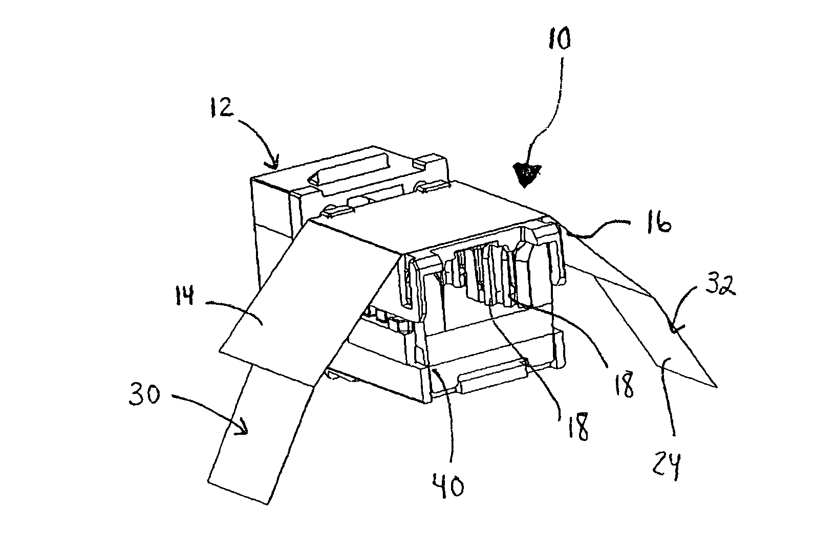
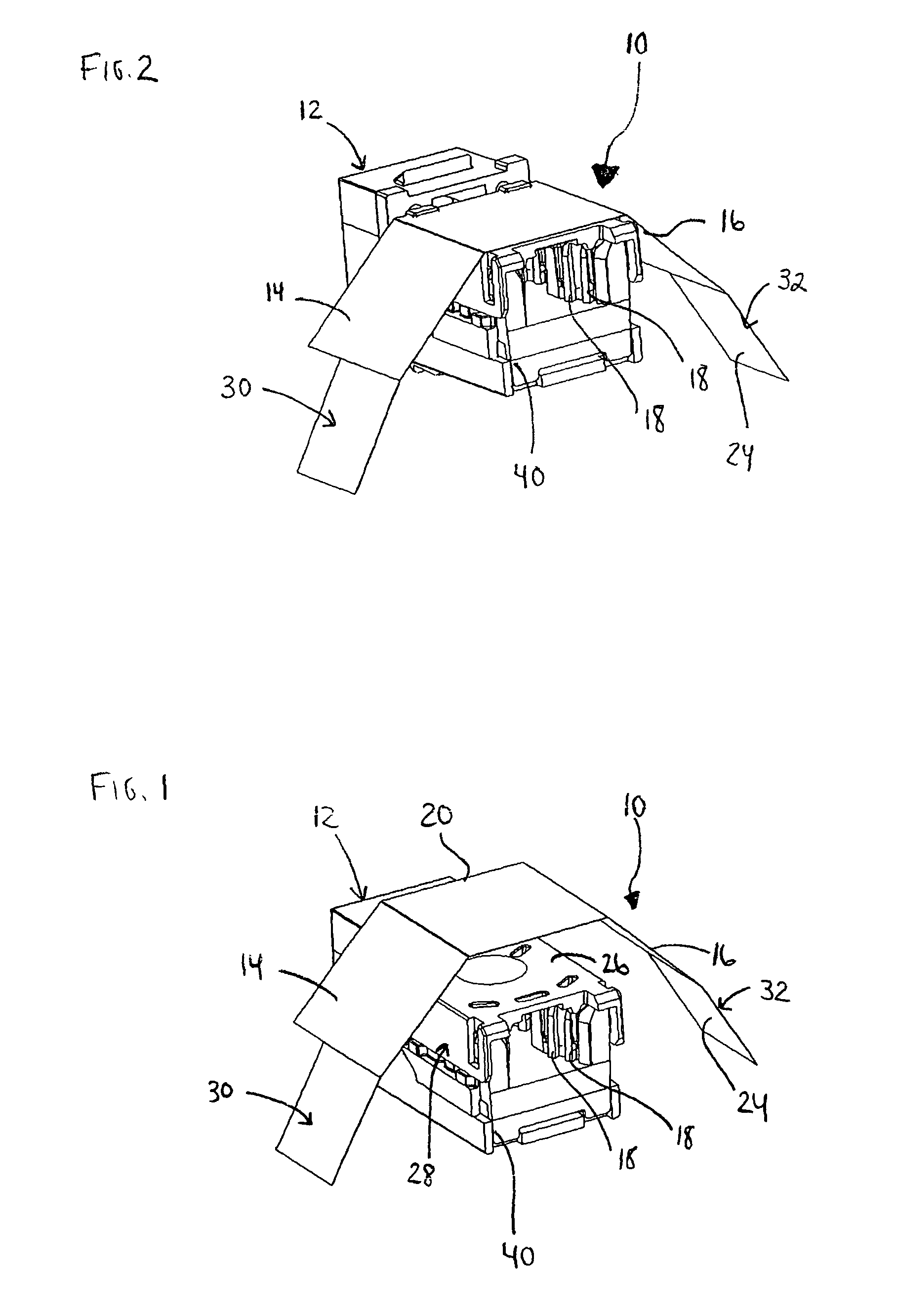
[0051]The fourth embodiment, involves the use of a cable shield, as seen in FIGS. 12-14. A shield 300 is an alternative to plating an adapter. The shield 300 surrounds the tip 312 of a cable 302 and a plurality of IDC towers 304 located on a panel 306. The shield 300 includes a first end 308 and a second end 310 having a second opening 314 larger than the first opening 316 of the first end 308. The first end 308 is the narrowest point of the shield 300 to fit around the cable 302. The main body 318 of the shield 300 gradually expands towards the second opening 314 that surrounds the IDC towers 304. The shield 300 can protect the IDC towers 304 at installation or subsequently as an addition to the panel 306. The cable 302 passes laterally through an opening, feeds into the shield 300, enabling the shield 300 to move up and envelop the IDC towers 304.

[0052]The shield 300 can be equipped with a longitudinal slot 320 extending from the first opening 316 along the main body 318 to the se...


PUM


Abstract

A conductive cover or shield for reducing crosstalk between a plurality of connectors arranged adjacent one another. A cover having a non-conductive interior surface and a conductive outer surface. The non-conductive surface is adhered to the exterior surface of a connector or a plurality of IDC towers for preventing crosstalk between adjacent connectors. Also, the cover can be form fitted and secured to the connectors, specifically, adhering to the corners to insulate any loose wires.

Description

CROSS-REFERENCE TO RELATED APPLICATIONS[0001]This application claims the benefit of U.S. Provisional Application 60 / 960,576 filed Oct. 4, 2007, which application is hereby incorporated by reference in its entirety.FIELD OF THE INVENTION[0002]The present invention relates to a conductive cover or shield for reducing crosstalk between connectors arranged in a side-by-side configuration. More particularly, the invention relates to a cover having a non-conductive interior surface disposed adjacent to a plurality of IDC towers and a conductive exterior surface for preventing crosstalk between adjacent connectors. Optionally, the conductive surface could be layered between multiple non-conductive surfaces.BACKGROUND[0003]Conventional cables and electrical connectors arranged in sets and in parallel are oftentimes too close together and result in inductive or capacitive interference therebetween. The proximity of the connectors is necessary because of the limited spacing within patch panel...

Claims


Application Information

Patent Timeline
Patent Type & Authority Patents(United States)
IPC IPC(8): H01R24/00
CPCH01R13/6461H01R13/6586H01R13/6598H01R4/2429H01R24/64
Inventor ABUGHAZALEH, SHADI A.O'CONNOR, DOUGLAS P.
Owner HUBBELL INC
Features
  • R&D
  • Intellectual Property
  • Life Sciences
  • Materials
  • Tech Scout
  • Unparalleled Data Quality
  • Higher Quality Content
  • 60% Fewer Hallucinations
Learn More