Utility tray for tripod

a technology for tripods and storage racks, which is applied to trays, instruments, machine supports, etc., can solve the problems of adding to the expense and complexity of removable shelves, and not typically including any type of permanently attached shelf or storage racks

Inactive Publication Date: 2011-05-31
ALMOND WILLIAM CHASE +1
View PDF44 Cites 40 Cited by
  • Summary
  • Abstract
  • Description
  • Claims
  • Application Information

AI Technical Summary

Problems solved by technology

As a result, these tripods do not typically include any type of permanently-attached shelf or storage tray despite the usefulness that a shelf or tr

Method used


Image

  • Utility tray for tripod
  • Utility tray for tripod
  • Utility tray for tripod

Examples


Embodiment Construction

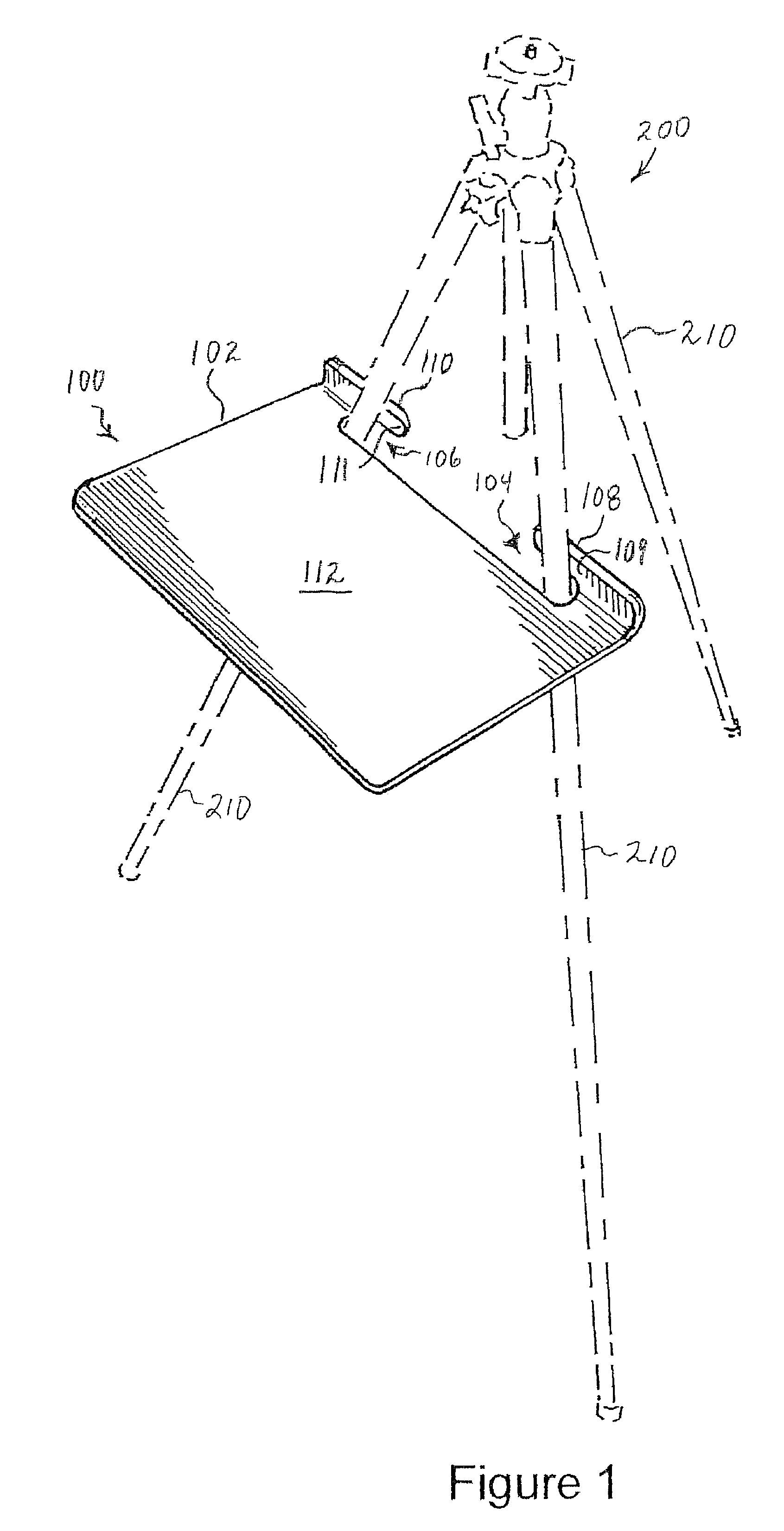
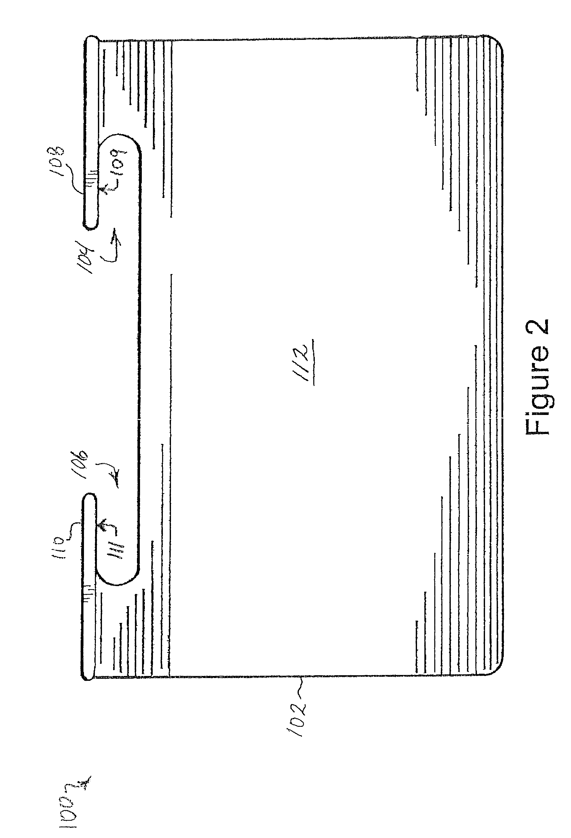
[0027]Referring first to FIGS. 1 and 2, FIG. 1 shows a tray assembly 100 mounted onto a tripod 200 (shown in phantom) and FIG. 2 shows a plan view of the tray assembly 100. The tray assembly 100 includes a shelf 102 that mounts onto two of the tripod legs 210 at slots 104, 106. The shelf 102 is supported in a cantilever fashion by a pair of support tabs 108, 110. The support tabs 108, 110 have respective contact surfaces 109, 111, and at least a portion of each of the contact surfaces 109, 111 is intended to contact a respective tripod leg 210 when the tray assembly 100 is installed. The shelf 102 hangs off the tripod 200 away from the tripod 200, thus providing a level, accessible work and storage surface 112 for an artist or other tripod user. A user can remove the tray assembly 100 from the tripod 200 by simply lifting the tray assembly 100 up and away from the tripod 200. Note that in a preferred embodiment, the entire contact surfaces 109, 111 extend substantially perpendicular...


PUM


Abstract

A removable tray assembly is disclosed for use with a tripod or easel. The tray assembly includes a shelf having a back edge, a front edge, and two side edges. The tray assembly also includes a pair of support tabs spaced from the back edge of the shelf by respective slots. The removable tray is attached to two legs of the tripod, with one leg passing through each slot. The support tabs contact the side of the tripod legs opposite the shelf and thereby support the shelf in a cantilever fashion.

Description

BACKGROUND[0001]1. Field of the Invention[0002]This invention relates in general to removable shelves or trays for use with portable tripods and easels.[0003]2. Description of Related Art[0004]Tripods have been in widespread use for many years. They are commonly used as a support for a number of different applications. For example, tripods are often used for cameras, telescopes, and easels. Many such tripods are designed to be collapsible and easily portable. As a result, these tripods do not typically include any type of permanently-attached shelf or storage tray despite the usefulness that a shelf or tray would provide.[0005]Because of this common shortcoming, various removable shelves have been introduced. For example, U.S. Pat. No. 6,240,857 to Elizer discloses a removable shelf assembly for use with a tripod or easel. However, the Elizer removable shelf requires support arms and clamps that add to the expense and complexity of the removable shelf. Thus, there remains a need in ...

Claims


Application Information

Patent Timeline
IPC IPC(8): A47B23/00
CPCA47B23/001G03B17/561F16M13/00F16M11/32F16M13/02
Inventor ALMOND, WILLIAM CHASECOLLINS, STEVEN SCOTT
Owner ALMOND WILLIAM CHASE
Why Eureka
Try Eureka