Method and apparatus for the detection of objects using electromagnetic wave attenuation patterns

a technology of electromagnetic wave attenuation and object detection, applied in the direction of communication jamming, measurement devices, instruments, etc., can solve the problems of extremely limited off-axis sensitivity by design, limited system, limited to certain electromagnetic bands, etc., and achieve the effect of increasing the percentage of attenuation

Inactive Publication Date: 2011-05-31
JG TECH LLC
View PDF22 Cites 36 Cited by
  • Summary
  • Abstract
  • Description
  • Claims
  • Application Information

AI Technical Summary

Benefits of technology

[0032]In order to collimate the microwaves for detection of small areas within the detection space, tubes may be used to limit the field of view that is seen by each detector, thus increasing the percentage attenuation caused by a Stealth Craft in that pixel of the Sky.

Problems solved by technology

It is noted that, in traditional systems, detection is limited to “line of sight”, possibly with predetermined reflections of the beam, and off axis sensitivity is extremely limited by design.
These systems, however, are limited to certain electromagnetic bands, for example mid- or near infrared to X-ray ranges.
As such, these systems are only employed in limited range applications, since beam propagation may be limited by atmospheric conditions or noise, and typically are difficult to accurately detect over long distances through the atmosphere.

Method used


Image

  • Method and apparatus for the detection of objects using electromagnetic wave attenuation patterns
  • Method and apparatus for the detection of objects using electromagnetic wave attenuation patterns
  • Method and apparatus for the detection of objects using electromagnetic wave attenuation patterns

Examples


Embodiment Construction

[0054]The preferred embodiments will now be described by way of example, in which like reference numerals indicate like elements.

Active Detection

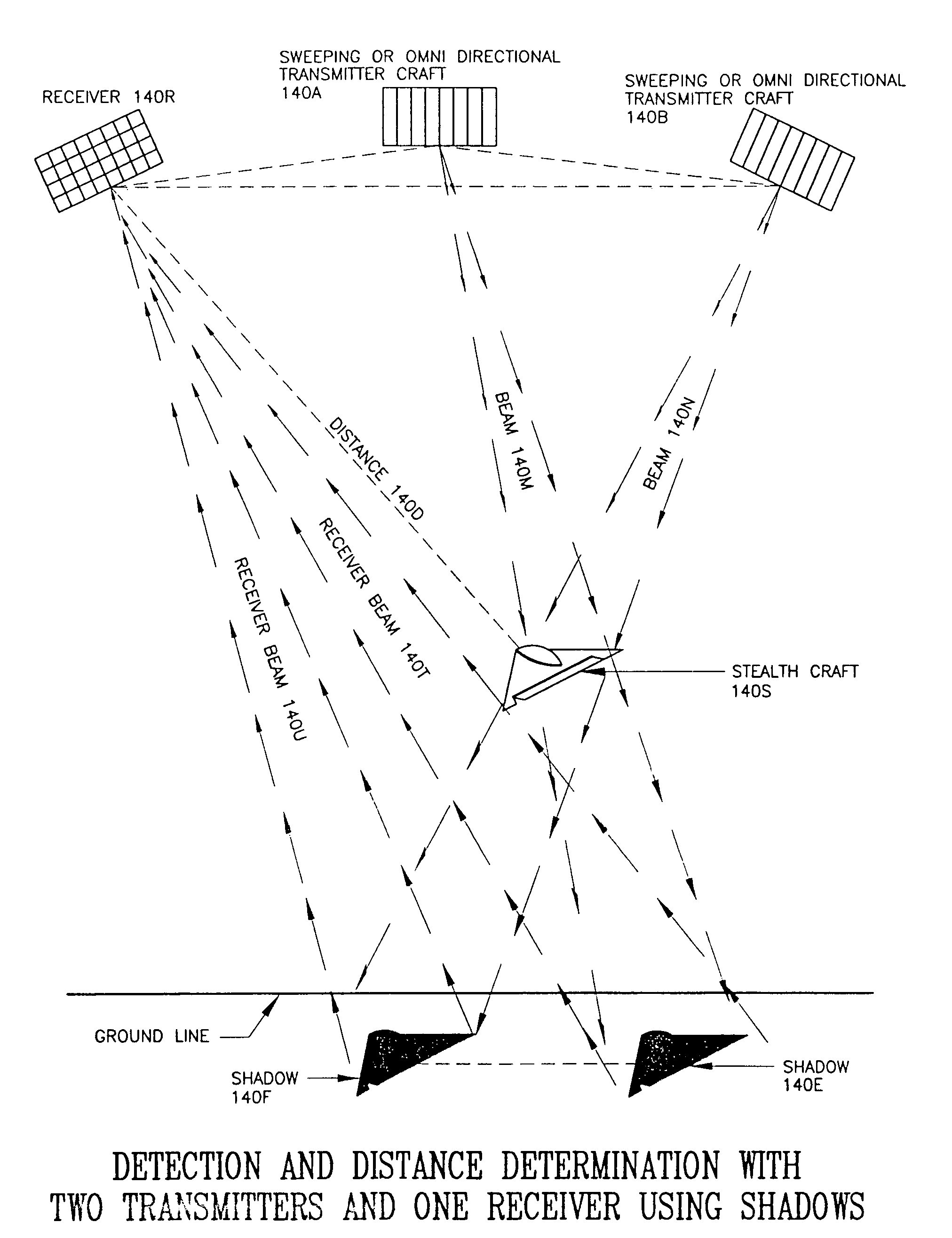
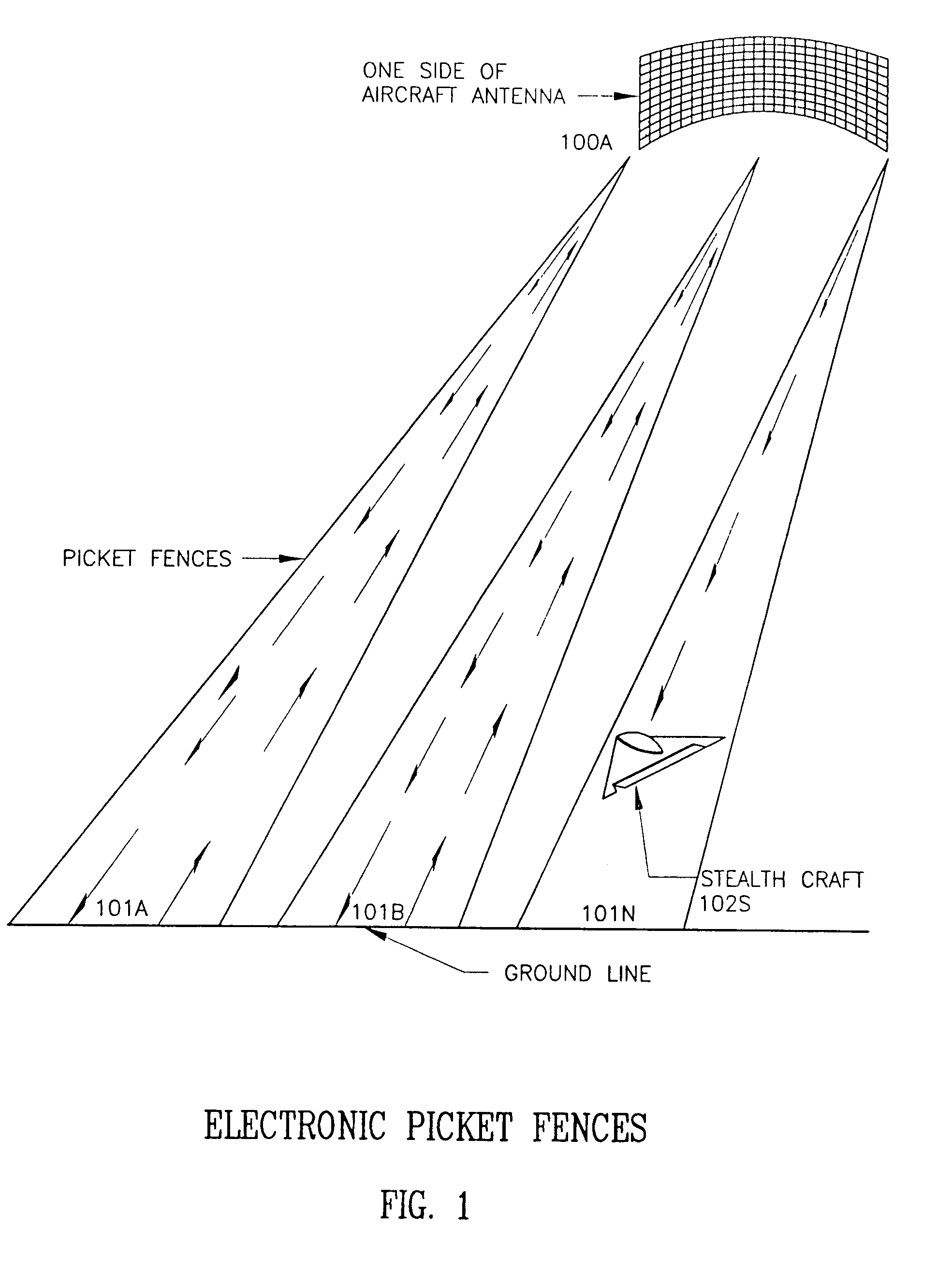
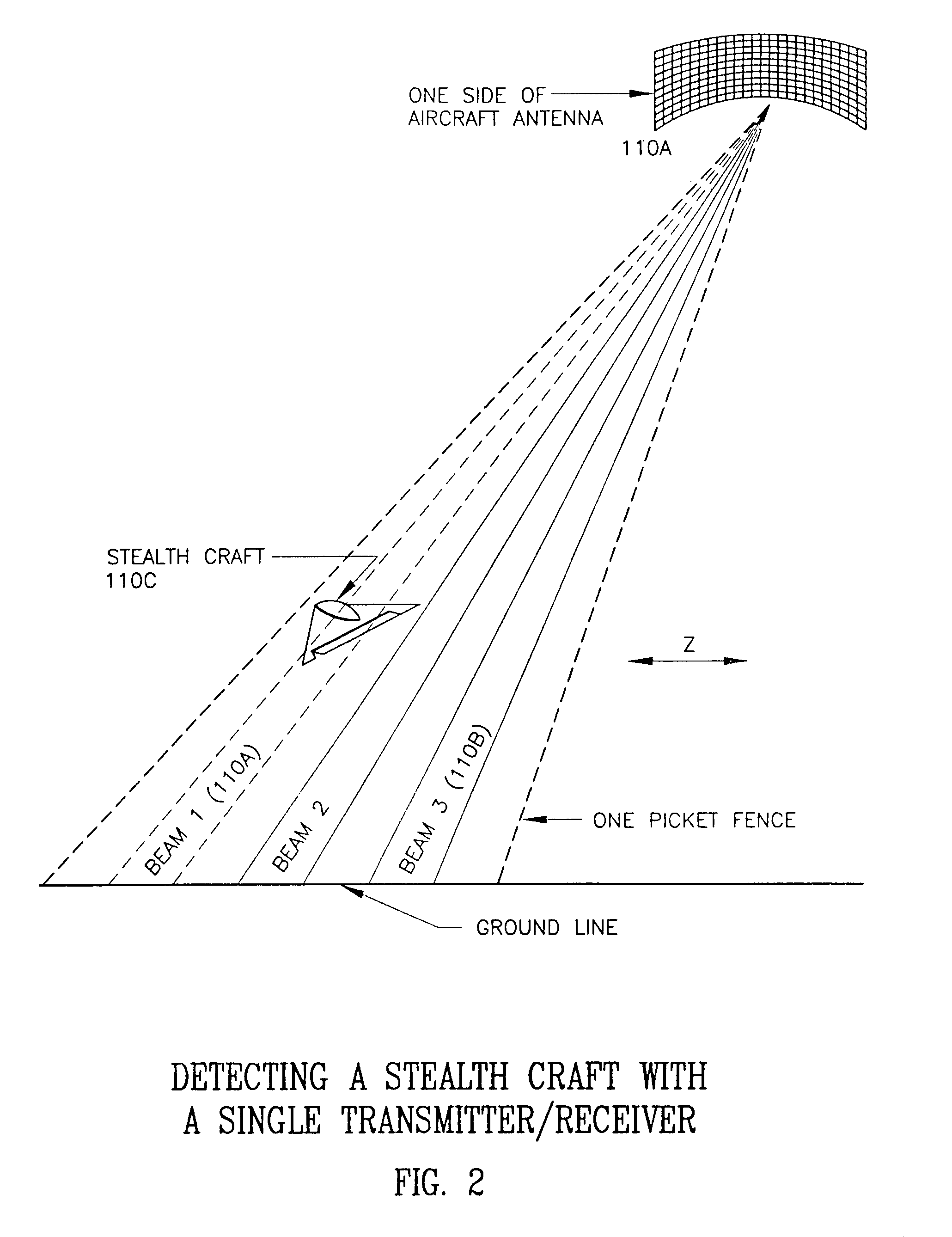
[0055]In standard active detection, a beam of electromagnetic energy, such as microwave, visible light, or infrared light (from a laser) is directed toward a target and the energy reflected from the target is used to detect the presence of the target, and to derive characteristics of the target, such as distance, bearing, speed, and size.

[0056]However, according to the present invention, negative radar, a microwave beam is bounced off a large reflector, such as the Earth, and the silhouette (or attenuation of the microwave) that the object produces against the beam or a reflection of the beam is detected. This method can also be used with non-stealth craft, since the Doppler shift of microwaves reflected from a non-stealth craft can be used to differentiate it from the microwave reflected from, e.g., the Earth, so that the microwaves reflec...


PUM


Abstract

A method for detecting an object, comprising the steps of defining expected characteristics of scattered electromagnetic radiation to be received at a receiver; attenuating at least a portion of electromagnetic radiation received at the receiver by a presence of an object within a path of electromagnetic information; and detecting the attenuation to indicate a presence of the object. The object may be a low radar profile object, such as a stealth aircraft. The electromagnetic radiation is preferably microwave, but may also be radio frequency or infrared. By using triangulation and other geometric techniques, distance and position of the object may be computed.

Description

BACKGROUND OF THE INVENTION[0001]Radar was developed in World War II to detect enemy aircraft. It has subsequently been refined to detect a large variety of objects, including ships, helicopters, satellites, and land vehicles. Radar systems typically work on the principle of bouncing microwave radiation off an object and analyzing the reflected signal (echo). The reflected signal can be used to develop information about the object, e.g., by measuring the round trip signal (echo) time the distance to the object can be determined, and by determining a Doppler shift of the echo a velocity of the object may be estimated. With sophisticated system design, object shape and size may be analyzed. Finally, a temporal analysis of sequential echoes may be used to detect a motion vector and characteristics of moving parts of the object.[0002]Radar systems thus emit an electromagnetic wave or pulse, and analyze a reflection pattern to determine a characteristic of the object, distinguishing the ...

Claims


Application Information

Patent Timeline
Patent Type & Authority Patents(United States)
IPC IPC(8): H04K3/00G01S13/88G01S13/00
CPCG01S7/292G01S13/48G01S13/04G01S13/02G01S13/003G01S13/08G01S13/449G01S13/88
Inventor GEER, JAMES L.
Owner JG TECH LLC
Why Eureka
Try Eureka