
Liquid crystal module with lamp socket having slits that receive tabs of lamp reflector

a technology of liquid crystal modules and lamp sockets, applied in the field of liquid crystal modules, can solve the problems of prone to affecting the operation of lighting and heating appliances, and requiring more maintenance and replacement, so as to achieve the effect of reliably preventing the misalignment of lamp sockets

Inactive Publication Date: 2011-06-07
FUNAI ELECTRIC CO LTD
View PDF10 Cites 3 Cited by
  • Summary
  • Abstract
  • Description
  • Claims
  • Application Information

AI Technical Summary

Benefits of technology

[0017]The present invention is conceived in light of the above-mentioned problems. One object of the present invention is to provide a liquid crystal module with which lamp socket misalignment can be reliably prevented.
[0019]With the liquid crystal module of the present invention, it is possible to provide a liquid crystal module with which lamp socket misalignment can be reliably prevented.

Problems solved by technology

Thus, the lamp sockets are prone to misalignment if the fixing protrusions are not securely fitted into the fixing holes during the fixing of the lamp sockets, or if the fixing protrusions come out of the fixing holes after the lamp reflector assembly is installed.
Thus, the threading of the screws leads to lower assembly efficiency and higher cost.
Furthermore, maintenance entails more work in replacing the cold cathode tube.
Thus, the socket main body is prone to misalignment.
Thus, attaching the sockets is unsafe and difficult.
Furthermore, an attachment structure such as this is unsuited to attaching sockets to ends of a slender lamp reflector having an ordinary open box section shape.
While this does reduce the number of screws used, it still entails troubles of threading the screw.
Thus, assembly efficiency becomes poor, and maintenance entails more work in replacing lamps.
Since the crimping has to be performed, assembly efficiency becomes poor and manufacturing cost cannot be reduced.

Method used


Image

  • Liquid crystal module with lamp socket having slits that receive tabs of lamp reflector
  • Liquid crystal module with lamp socket having slits that receive tabs of lamp reflector
  • Liquid crystal module with lamp socket having slits that receive tabs of lamp reflector

Examples


Embodiment Construction

[0032]A preferred embodiment of the present invention will now be explained with reference to the drawings. It will be apparent to those skilled in the art from this disclosure that the following descriptions of the preferred embodiment of the present invention is provided for illustration only and not for the purpose of limiting the invention as defined by the appended claims and their equivalents.

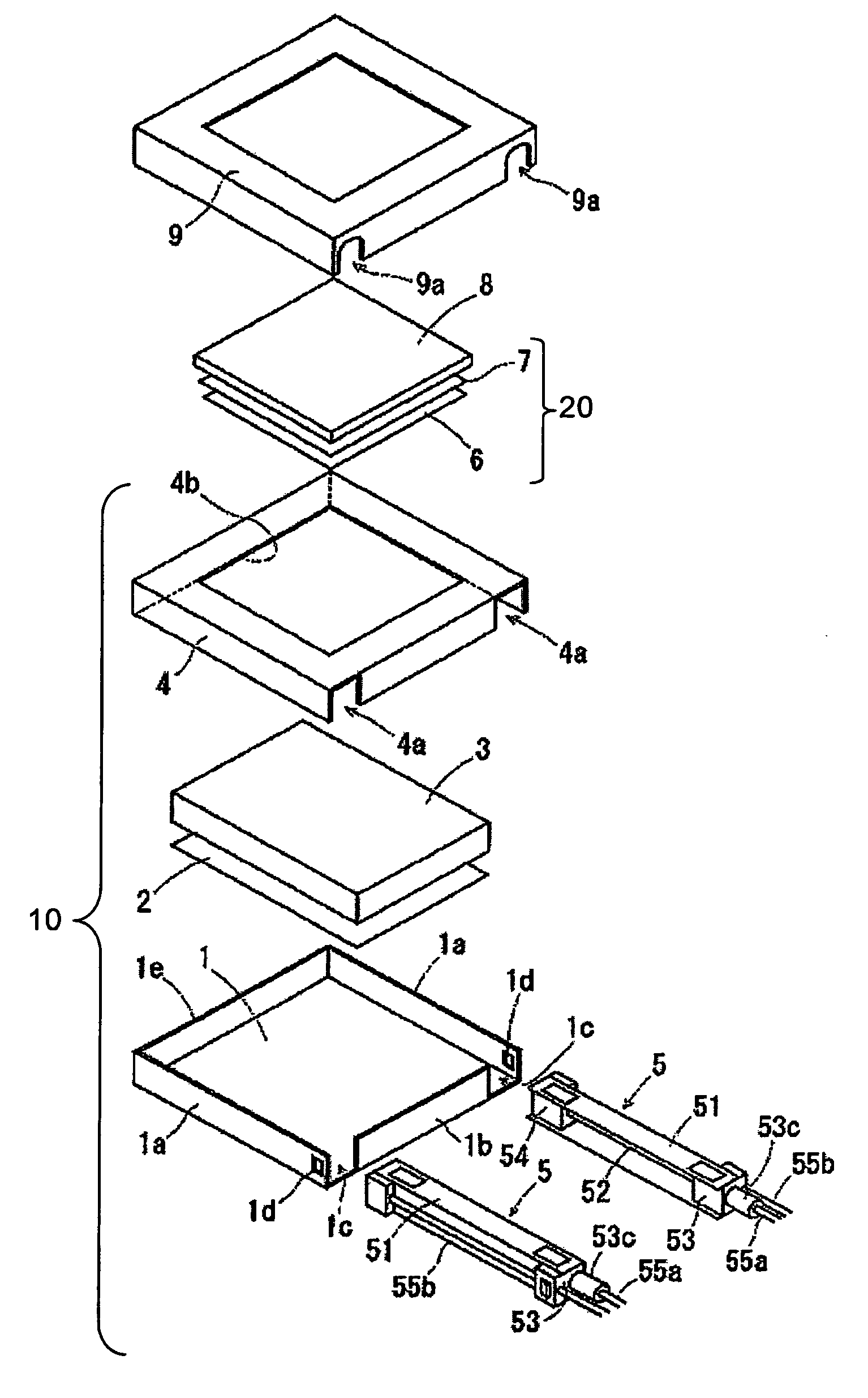
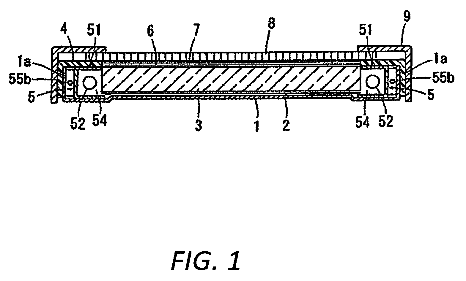
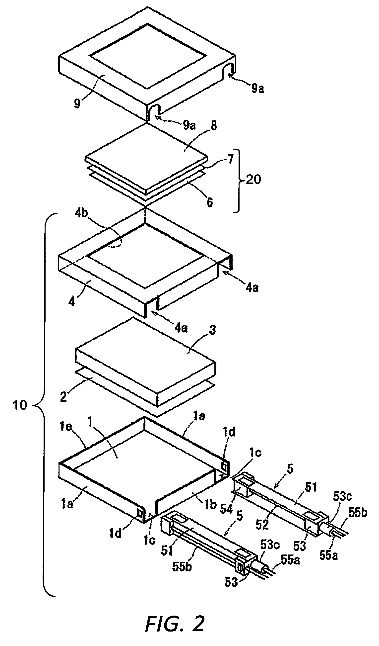
[0033]As shown in FIGS. 1 and 2, a liquid crystal module includes a back light unit 10, an optical sheet 20, a liquid crystal panel 8 and a bezel 9.

[0034]The back light unit 10 is disposed on a rear side of the liquid crystal panel 8. The back light unit 10 is a side-edge-lighted type back light unit. The back light unit 10 has a rear frame 1, a light reflecting sheet 2, a light guide plate 3, a front frame 4 and a pair of left and right lamp reflector assemblies 5. The rear frame 1 and the front frame 4 house the light reflecting sheet 2, the light guide plate 3 and the left and right la...


PUM

PropertyMeasurementUnit
liquid crystal moduleaaaaaaaaaa
timeaaaaaaaaaa
shapeaaaaaaaaaa

Abstract

A liquid crystal module includes a liquid crystal panel and a back light unit. The back light unit has a rear frame, a light guide plate and a lamp reflector assembly. The lamp reflector assembly including a light source, a lamp reflector and a lamp socket. The lamp reflector has a front plate, a rear plate and a side plate with a tab. At least one of the front plate and the rear plate has a fixing hole. The lamp socket has a fixing protrusion that is fitted into the fixing hole of the lamp reflector, and a slit that receives the tab of the lamp reflector.

Description

CROSS-REFERENCE TO RELATED APPLICATIONS[0001]This application claims priority to Japanese Patent Application No. 2007-163258 filed on Jun. 21, 2007. The entire disclosure of Japanese Patent Application No. 2007-163258 is hereby incorporated herein by reference.BACKGROUND OF THE INVENTION[0002]1. Field of the Invention[0003]The present invention generally relates to a liquid crystal module. More specifically, the present invention relates to a liquid crystal module having a back light unit.[0004]2. Background Information[0005]A conventional liquid crystal module includes a liquid crystal panel and a back light unit. The back light unit is disposed on a rear side of the liquid crystal panel. The back light unit has a rear frame, a light guide plate and a lamp reflector assembly. The rear frame houses the light guide plate. The lamp reflector assembly includes a cold cathode tube, a lamp reflector and a plurality of lamp sockets. The cold cathode tube is disposed on an inside of the la...

Claims


Application Information

Patent Timeline
Patent Type & Authority Patents(United States)
IPC IPC(8): G02F1/1335G01D11/28F21V7/04
CPCG02B6/0031G02B6/009G02B6/0071
Inventor TANAKA, KAZUYA
Owner FUNAI ELECTRIC CO LTD
Learn More