Embossing or bonding device containing facetted impression elements

a bonding device and facet technology, applied in the direction of threaded fasteners, screws, bolts, etc., can solve the problems of general weakening of sheet materials, affecting the production efficiency of equipment used to run the process, and affecting the quality of finished products, etc., to achieve the effect of reducing the occurrence of tearing, fracturing, or fatiguing of materials

Inactive Publication Date: 2011-07-05
KIMBERLY-CLARK WORLDWIDE INC
View PDF59 Cites 53 Cited by
  • Summary
  • Abstract
  • Description
  • Claims
  • Application Information

AI Technical Summary

Benefits of technology

[0007]In general, the present disclosure is directed to an embossing or bonding process in which a sheet material is contacted with a raised element that is configured to form impressions, such as densified areas, in the sheet material without substantially damaging the material. For instance, the raised element has a facetted design that minimizes occurrences of tearing, fracturing, or fatiguing of the material as the material is fed through the process.
[0009]For example, in one embodiment, a compound angle is formed around the top surface of the impression element which has been found to significantly reduce fracturing of the sheet material as the sheet material is contacted with the rotating anvil roller. In particular, the chamfered surfaces form release angles on the impression element as a sheet material is transferring in and out of contact with the raised element. In other words, the chamfered surfaces have been found to lessen a drag effect between the edges of the impression element and the sheet material during contact.

Problems solved by technology

In these types of processes, a reoccurring problem is that the raised elements on the rotating roller may have sharp edges that cause tearing, fracturing, fatiguing, or general weakening of the sheet material as the material is fed through the process.
For example, the sharp edges may have a tendency to damage the sheet material as the sheet material contacts the leading edge of the raised element and as the sheet material contacts the trailing edge of the raised element.
Such attempts, however, have not fully eradicated the problem and / or have added great cost in producing the equipment used to run the process.

Method used


Image

  • Embossing or bonding device containing facetted impression elements
  • Embossing or bonding device containing facetted impression elements
  • Embossing or bonding device containing facetted impression elements

Examples


Embodiment Construction

[0031]It is to be understood by one of ordinary skill in the art that the present discussion is a description of exemplary embodiments only, and is not intended as limiting the broader aspects of the present invention.

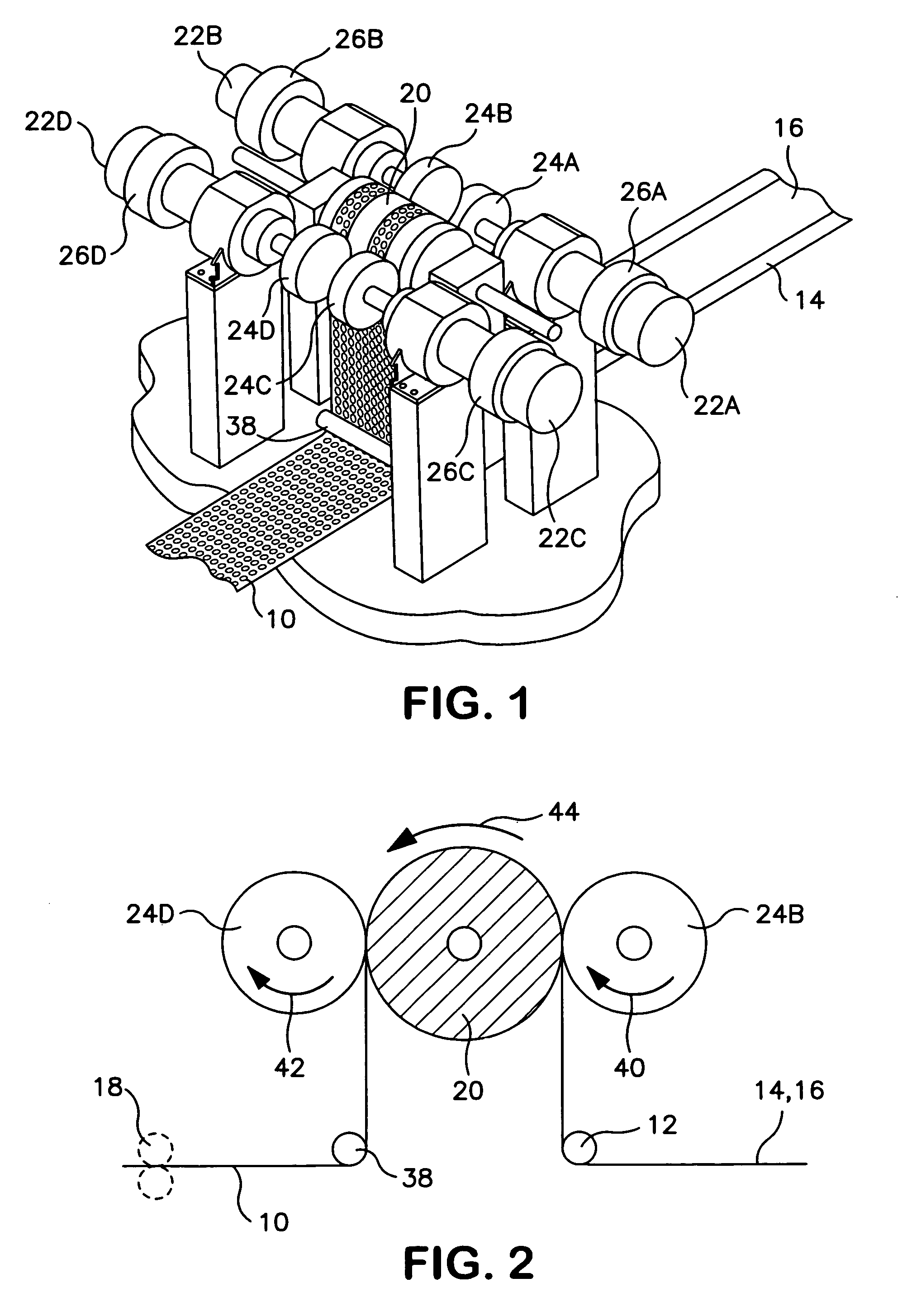
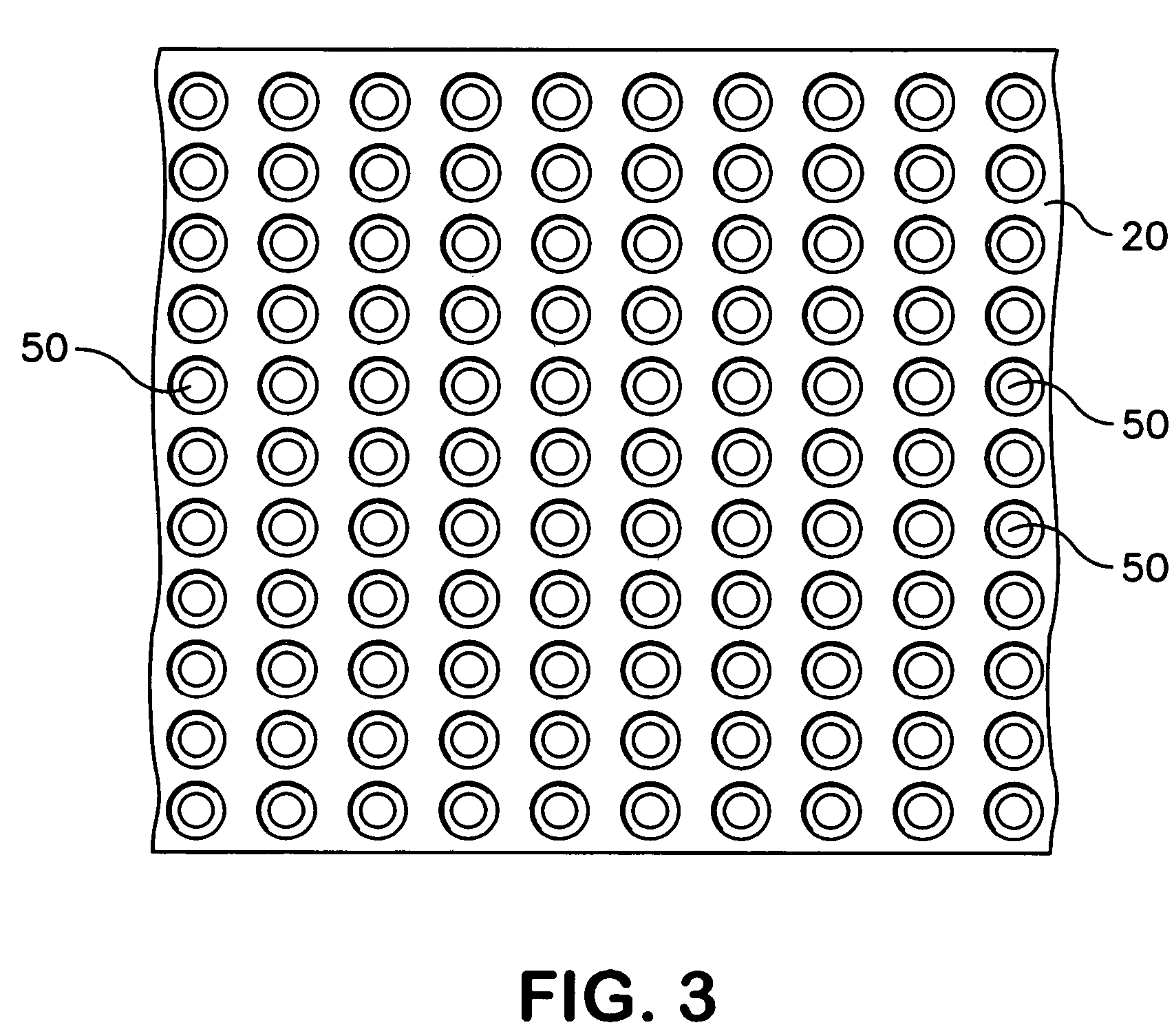
[0032]In general, the present disclosure is directed to apparatus and processes for forming embossments and / or bonding areas into sheet materials. The sheet materials are contacted with an anvil roll containing at least one facetted impression element made in accordance with the present disclosure. For example, in one embodiment, a plurality of facetted impression elements form raised projections on the anvil roll according to a particular pattern. The sheet materials may be contacted with the anvil roll as the anvil roll is rotating in order to form the densified areas.

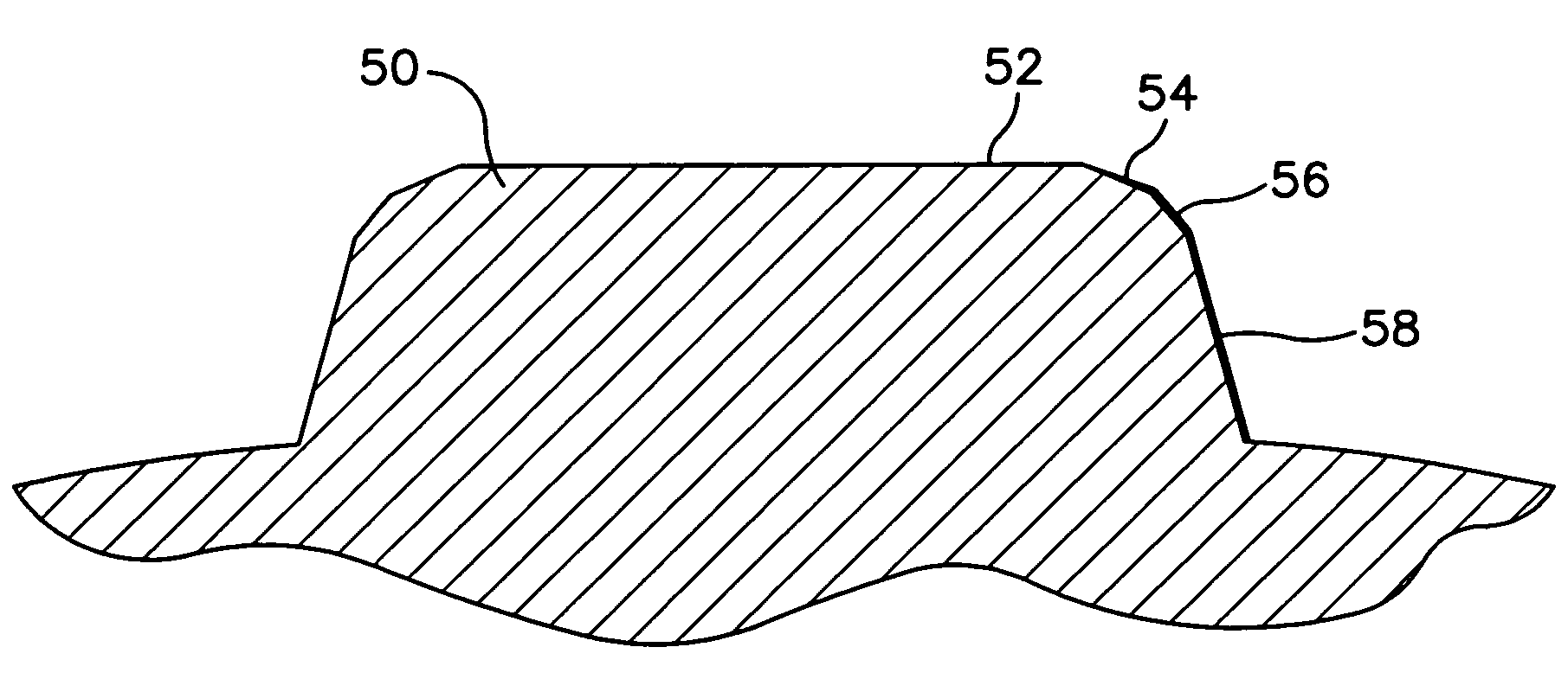
[0033]In accordance with the present disclosure, the facetted impression elements include a top surface that is surrounded by at least one, such as at least two different chamfered surfaces. The chamfer...


PUM

PropertyMeasurementUnit
angleaaaaaaaaaa
angleaaaaaaaaaa
angleaaaaaaaaaa

Abstract

Facetted impression elements are disclosed. The impression elements can be located, for instance, on an anvil roll and may be used during an embossing or bonding process. The impression elements include at least two chamfered surfaces that at least partially surround the top surface. The chamfered surfaces are at an angle to the top surface that lower and reduce drag that may occur between the impression element and a sheet of material as the impression element enters and exits the sheet. In one embodiment, the impression element includes a first chamfered surface having an angle of from about 5° to about 40° and a second chamfered surface having an angle of from about 40° to about 70°.

Description

BACKGROUND OF THE INVENTION[0001]During the manufacture of many consumable products, sheet materials are subjected to an embossing process or to a bonding process in which the sheet materials are pressed against a rotating roll having a plurality of raised elements. The raised elements form densified areas in the sheet material which can be, for instance, embossments or bonding areas.[0002]The sheet materials are subjected to a process as described above for various different reasons. For instance, in some embodiments, the sheet materials are embossed solely to improve the aesthetic appeal of the product. For instance, many tissue products, such as paper towels and bath tissues, are embossed with decorative designs.[0003]In other embodiments, the sheet materials may comprise a plurality of layers and the densified areas are used to bond the different layers together. For instance, the different layers contained within the sheet material may be made from thermoplastic polymers that s...

Claims


Application Information

Patent Timeline
Patent Type & Authority Patents(United States)
IPC IPC(8): B41F19/02B44B5/02
CPCB31F1/07B29C59/04B29C65/087B29C65/18B29C66/1122B29C66/21B29C66/3452B29C66/45B29C66/4722B29C66/81433B29C66/81467B29C66/81469B29C66/83411B29C66/83413B29C66/83511B31F2201/0789B29L2031/4878B29C65/26B29C65/30B29C66/433B29C66/7294B29C66/7392B29C66/81419B29C66/81429B29C66/727B29C66/729B29C66/73921B31F2201/0738
Inventor BLENKE, TIMOTHY J.SCHLINZ, DANIEL R.
Owner KIMBERLY-CLARK WORLDWIDE INC
Why Eureka
Try Eureka