

Cup and cone feed distributor
- Summary
- Abstract
- Description
- Claims
- Application Information
AI Technical Summary
Benefits of technology
Problems solved by technology
Method used
Image

Examples
Embodiment Construction
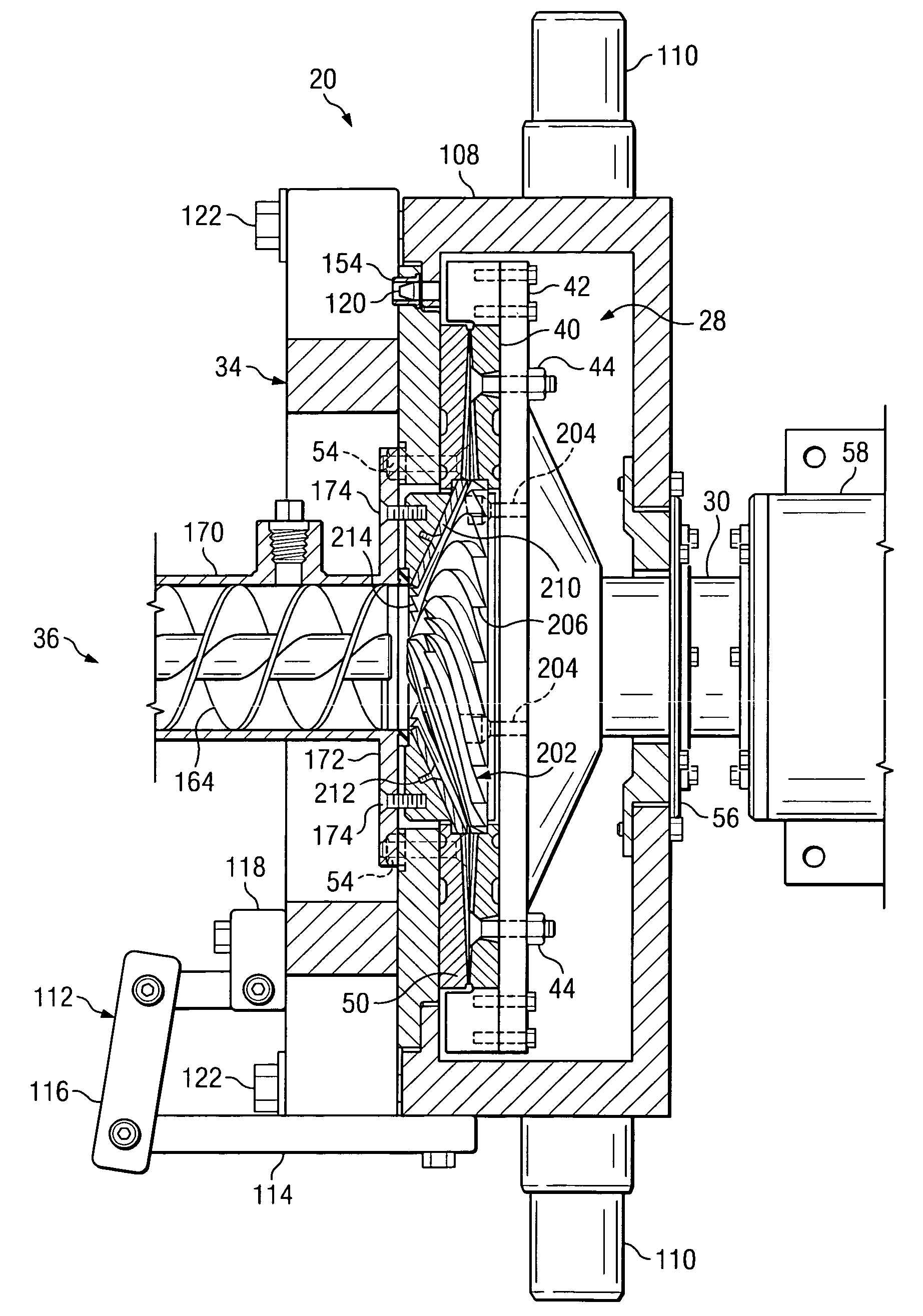
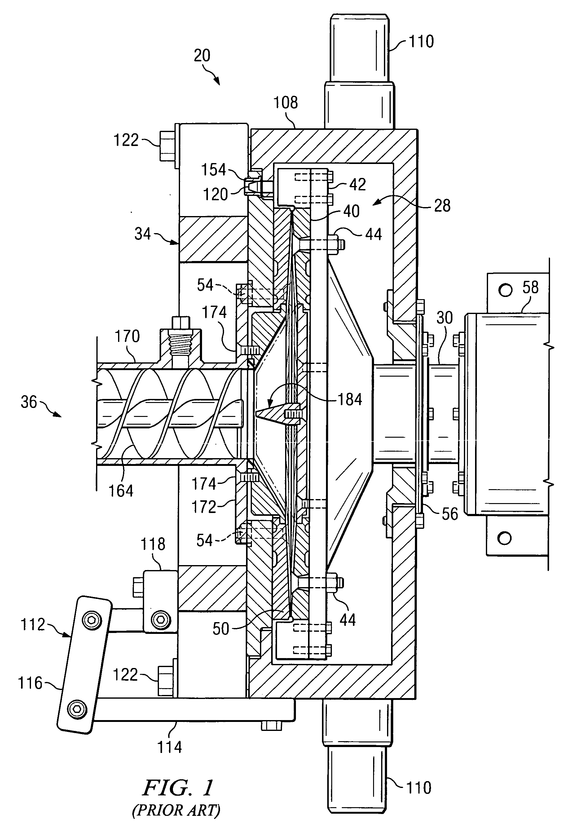
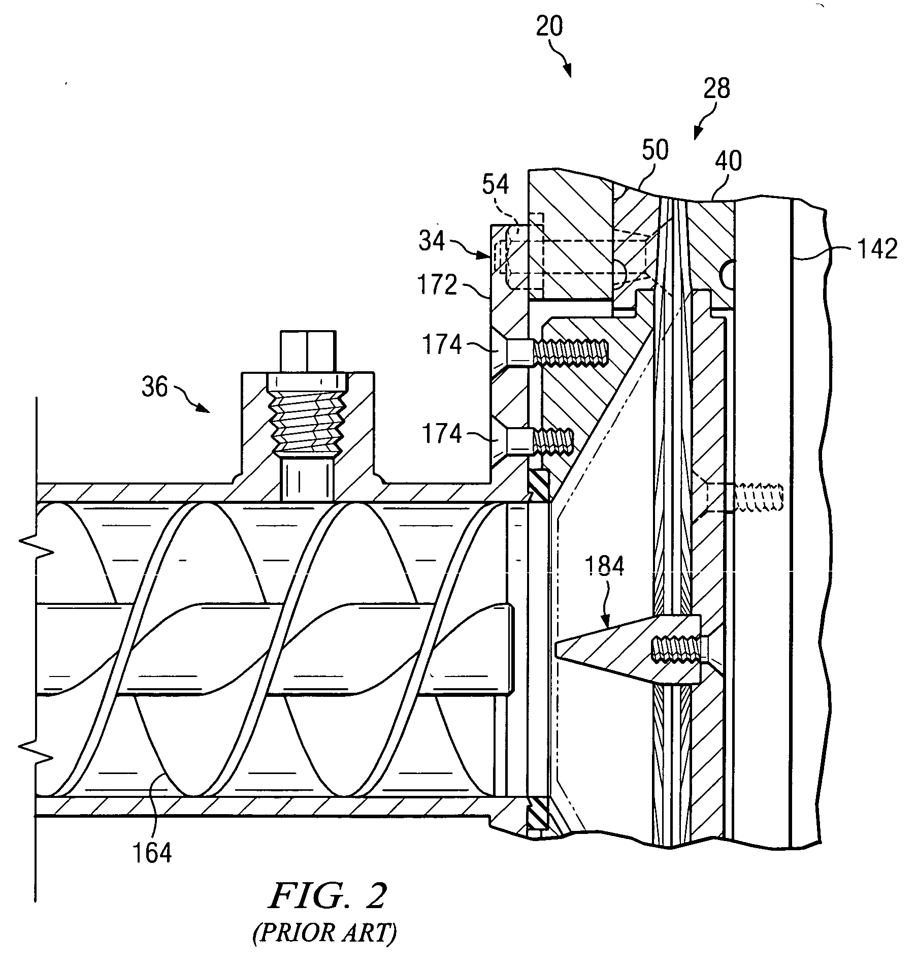
[0019] Referring specifically to FIGS. 5 through 8, there is shown the grinding chamber 28 comprising a first embodiment of the present invention which improves upon and may be used in conjunction with the grinding apparatus 20 shown in U.S. Pat. Nos. 6,322,013, 6,209,813, and 5,927,628 and described in detail therein.
[0020] Referring specifically to FIGS. 5 and 6, the grinding chamber 28 comprises a driven grinding member 40 and a fixed grinding member 50, as described in the aforementioned patents. A cone 202 for distributing foodstuff radially outward for engagement between the grinding members 40 and 50 is secured in the center of the driven grinding member 40 by fasteners 204 such that the cone 202 rotates with the driven grinding member 40. The cone 202 may be formed from a metal having a Rockwell C hardness of 30 or greater, or may be formed from other rigid materials known to those skilled in the art and suitable for use in the food processing industry. The cone 202 has spi...
PUM
 Abstract
Description
Claims
Application Information