Cutting roll cartridge for modular installation in a cutting roll assembly

Active Publication Date: 2020-07-14
AKRON STEEL FABTORS
View PDF8 Cites 0 Cited by
  • Summary
  • Abstract
  • Description
  • Claims
  • Application Information

AI Technical Summary

Benefits of technology

[0005]It is thus an object of one aspect of the present invention to reduce downtim

Problems solved by technology

While the cutters generally disclosed by the '628 patent are useful machines, the cutting blades thereof experience wear as a result of extended use.
Such repair or replacement results in the as

Method used


Image

  • Cutting roll cartridge for modular installation in a cutting roll assembly
  • Cutting roll cartridge for modular installation in a cutting roll assembly
  • Cutting roll cartridge for modular installation in a cutting roll assembly

Examples


Example

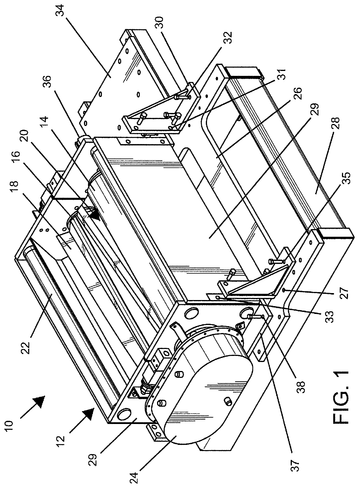
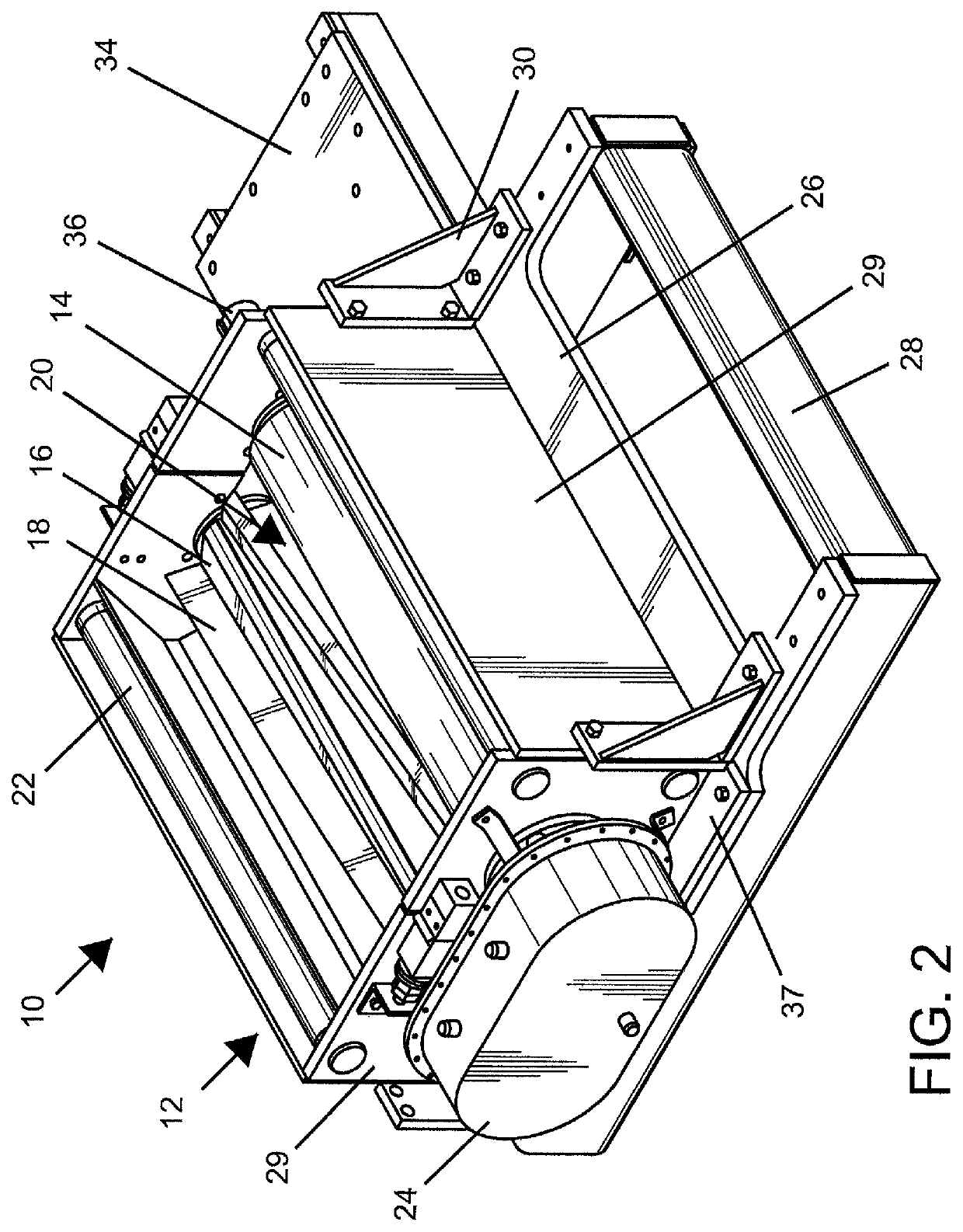
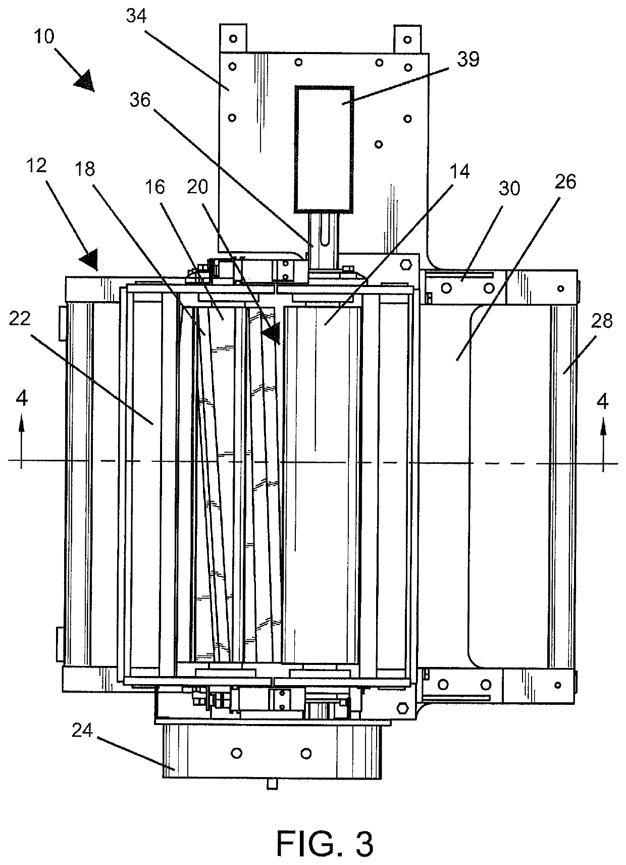
[0022]A cutting roll assembly for severing lengths of material into shorter, predetermined lengths is generally indicated by the numeral 10 and includes a cutting roll cartridge, generally indicated by the numeral 12, a base 26, a frame 28, and a plate 34.

[0023]Cutting roll cartridge 12 includes an anvil roll 14 and a cutter roll 16 having cutter blades 18. Anvil roll 14 and cutter roll 16 are rotatably mounted in cutting roll cartridge 12 and are oppositely rotating such that anvil roll 14 serves as an anvil against which the material is cut by cutter blades 18. Four cutter blades 18 are illustrated herein, but one skilled in the art will appreciate that any useful number of cutter blades could be used. The material to be cut into shorter lengths is fed in between anvil roll 14 and cutter roll 16 at a feed location, generally indicated by the numeral 20. Means for controlling the spacing and amount of movement upon a cutting action are generally indicated by the numeral 41 (FIG. 6)...


PUM


Abstract

A cutting roll assembly 10 for severing pieces from a length of material and advanced into proximity thereto includes a cutting roll cartridge 12 removably attached to an associated base 26 and frame 28. The cutting roll cartridge 12 includes a cutter roll 16 carrying at least one cutter blade 18 on its periphery and an anvil roll 14 used to cut material thereagainst as material is advanced between the rolls 16, 18. When the cutters 18 need repair, the cutting roll cartridge 12 is readily removable from the associated frame 28 and base 26 and replaceable by an identical cartridge to reduce downtime of the associated equipment.

Description

CROSS-REFERENCE TO RELATED APPLICATION[0001]This application is a division of U.S. patent application Ser. No. 14 / 317,270 filed on Jun. 27, 2014, which claimed priority from U.S. Provisional Patent Application Ser. No. 61 / 840,000 filed Jun. 27, 2013, entitled A Modular Cutting Roll Assembly, the entire contents of both which are incorporated herein by reference.TECHNICAL FIELD[0002]The present invention relates, in general, to a cutting roll assembly for use with a loading conveyor in which lengths of material are advanced along the conveyor to a cutting point and then severed into predetermined lengths for eventual further processing. More particularly, this invention relates to a cutting roll assembly having a cutting roll cartridge where the cutting roll cartridge can be modularly installed within the cutting roll assembly.BACKGROUND[0003]It has long been known that rotary cutters can be utilized to sever substantially endless lengths of material into predetermined lengths for fe...

Claims


Application Information

Patent Timeline
IPC IPC(8): B26D7/26B26F1/38
CPCB26F1/384B26D7/2614B26D7/2628
Inventor FLINNER, JR., VICTOR JAYKLINE, KEVIN R.POOLE, LEONPOPPLEWELL, RAYMOND JOHNSULTZBAUGH, JEFFREY MONROEWILMOTH, TIMOTHY ALAN
Owner AKRON STEEL FABTORS
Why Eureka
Try Eureka