
Fluid union apparatus and method

Active Publication Date: 2019-11-21
SETCO SALES
View PDF0 Cites 1 Cited by
  • Summary
  • Abstract
  • Description
  • Claims
  • Application Information

AI Technical Summary

Benefits of technology

The invention aims to solve issues related to the useful life of a fluid union, as well as minimize potential for seizing and flooding. The technical effects of the invention include reducing downtime, ensuring optimal operation of the spindle and minimizing the occurrence of flooding.

Problems solved by technology

However, directing coolant into a rotating shaft from a stationary source without leaking into undesired locations presents many challenges.
However, performance of such seals is limited by fluid pressure and shaft rotational speed.
In this regard, too much pressure can destroy the seals and overload the bearings with a piston-like force, and too much speed can generate excessive heat and wear on the seals.
These limitations render such seals unsuitable for applications with demanding, i.e. relatively high, rotational speed and / or fluid pressure requirements.
Such seals require very tight tolerances to minimize such control leakage, especially at high pressures, and are also subject to limitations based on union shaft size and pressure.
Although the use of a longer narrow gap could reduce the jet velocity of the leak, and would theoretically thereby lower the erosive effects and extend the life of the fluid union, a longer gap would also likely present one or more alignment problems.
Such problems can result in seizing of the components during rotation.
Labyrinth seals become ineffective when the internal cavity floods.
Traditional rubbing seals are not suitable alternatives due to high heat generation and the wear that is typically caused at high speeds.

Method used


Image

  • Fluid union apparatus and method
  • Fluid union apparatus and method
  • Fluid union apparatus and method

Examples


Embodiment Construction

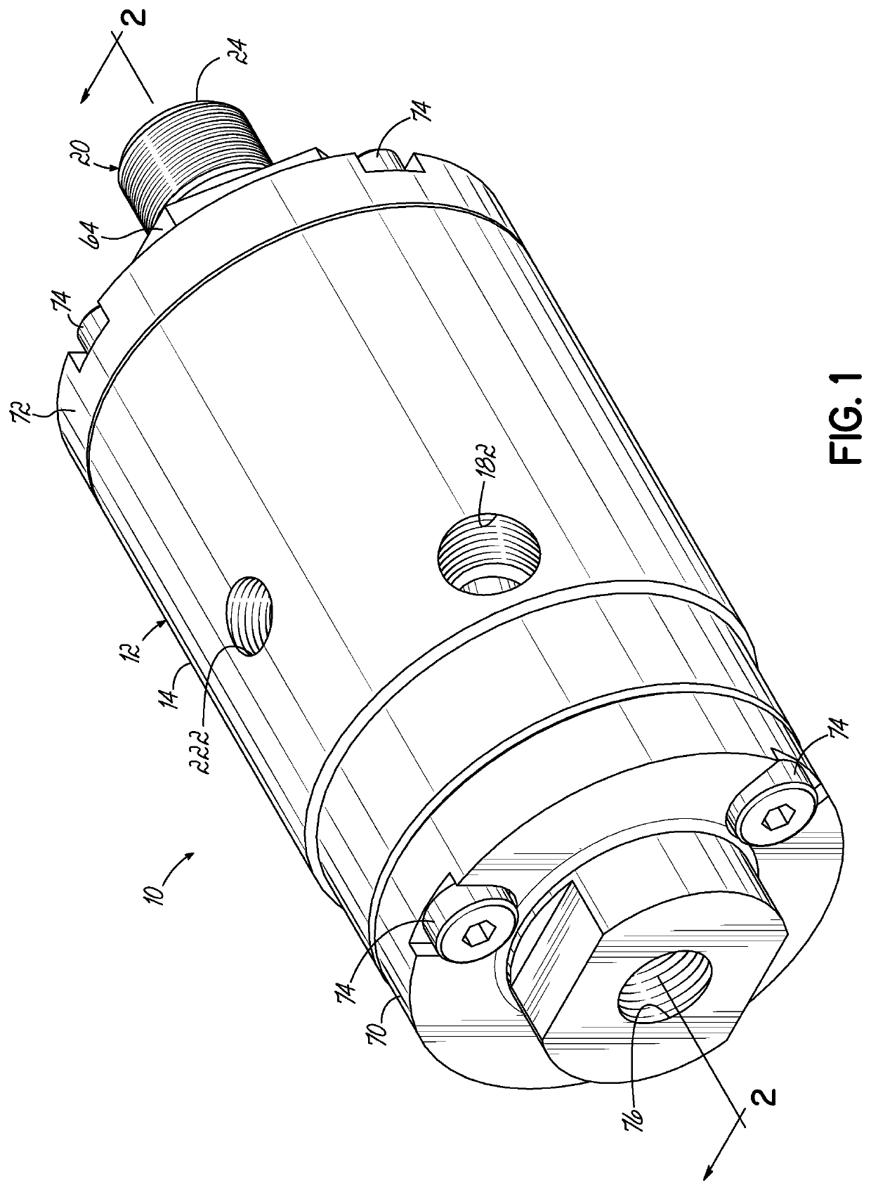
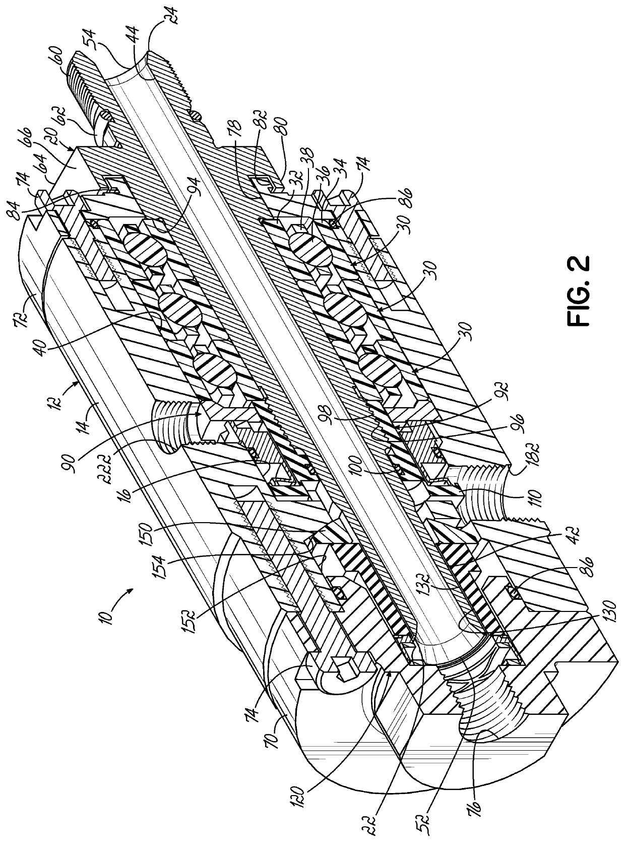
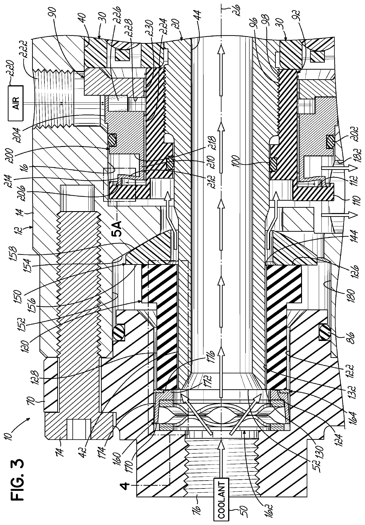
[0038]With reference to FIGS. 1-5B, an exemplary fluid union 10 for transferring a pressurized fluid from a stationary source into a rotating spindle shaft is shown in accordance with one embodiment of the present invention. As set forth in further detail below, the fluid union 10 is capable of achieving a longer life than prior art fluid unions, even when subjected to the harsh combination of high fluid pressure and high rotational speed. In this regard, the fluid union 10 includes a primary seal provided by at least one long narrow gap that maintains accurate alignment to avoid seizing of the components. The fluid union 10 also includes a secondary seal provided at least in part by a flexible lip configured to at least partially abrade on a rotating contact surface for providing a very light contact force therebetween. The features of the fluid union 10 are set forth in further detail below to clarify each of these functional advantages and other benefits provided in this disclosu...


PUM

PropertyMeasurementUnit
Widthaaaaaaaaaa
Widthaaaaaaaaaa
Flow rateaaaaaaaaaa

Abstract

A device for transferring a pressurized fluid from a stationary source into a rotating spindle shaft includes a stationary housing including an internal socket having a socket wall and a rotatable shaft extending into the socket. The shaft includes an outer surface and a shaft bore having inlet and outlet ends. The device includes a washer positioned over the shaft and including a first flat side surface and a second side surface having at least a portion angled with respect to the first flat side surface in operative contact with the socket wall. The device includes a bushing positioned over the shaft and including a bore having an inner surface spaced apart from the outer surface of the shaft by a gap. The bushing includes a first end surface proximate the inlet end and a second end surface in operative contact with the first flat side surface of the washer.

Description

FIELD OF THE INVENTION[0001]The present invention relates generally to machine spindles and, more particularly, to an apparatus for transferring a pressurized fluid from a stationary source into a rotating spindle shaft.BACKGROUND OF THE INVENTION[0002]Machine spindles are manufactured in a variety of configurations. Typically, machine spindles include three major components: a rotating spindle shaft, a stationary structure or housing that contains the shaft, and bearings that support the shaft and allow the shaft to rotate within the housing. The rotating spindle shaft usually holds a tool at one end (i.e., the work area) for performing a physical operation such as material removal, positioning, winding, flinging, etc. Many operations require the use of coolant or other fluids to clear the work area of debris and / or to provide heat removal. One pathway for introducing such fluid into the work area is through the center of the rotating spindle shaft and through the tooling into the ...

Claims


Application Information

Patent Timeline
IPC IPC(8): F16L27/08B23Q11/10F16C33/76F16C33/78
CPCF16C33/762F16L27/0828F16C2322/39F16C33/7886B23Q11/103B23Q11/1015F16J15/002
Inventor HOETING, STEPHEN CHARLESWHITE, JUSTIN ANTHONY
Owner SETCO SALES
Learn More