Slag door for a melting furnace

Active Publication Date: 2020-10-01
DANIELI & C OFF MEC SPA
View PDF0 Cites 0 Cited by
  • Summary
  • Abstract
  • Description
  • Claims
  • Application Information

AI Technical Summary

Benefits of technology

[0036]Advantageously, by removing the slag at the same time as the tapping of the steel, this method allows

Problems solved by technology

In addition to the premature exit of slag, or of scrap during the process, one of the problems that are found in the melting processes in this type of furnaces is that the slag tends to accumulate in the tunnel, or in correspondence with the threshold of the slag door, or it also adheres to the door itself, creating encrustations and deposits that hinder the extraction of the slag or the insertion through the door of material useful for the melting process.
This can cause an incorrect functioning and an incorrect and incomplete closure of the slag door, causing possible air infiltrations following the depression acting inside the shell, with a consequent lower efficiency of the furnace, since the slag and the electrodes thus tend to oxidize more.
In addition, this can cause possible safety hazards for operators following splashes or explosions.
This solution is very dangerous for the operator and it often has to be carried out only after an adequate cooling of the slag, so as to not increase the safety hazards for the operator.
However, sometimes, the removal of the slag has to necessarily be carried out with the furnace active, thus causing the problems and risks indicated above.
This solution also increases the downtime between one charge of scrap into the furnace and the next, causing an increase in costs and a decrease in productivity.
Howev

Method used


Image

  • Slag door for a melting furnace
  • Slag door for a melting furnace
  • Slag door for a melting furnace

Examples


Example

[0041]To facilitate comprehension, the same reference numbers have been used, where possible, to identify identical common elements in the drawings. It is understood that elements and characteristics of one embodiment can conveniently be incorporated into other embodiments without further clarifications.

DETAILED DESCRIPTION OF SOME EMBODIMENTS

[0042]We will now refer in detail to the various embodiments of the present invention, of which one or more examples are shown in the attached drawings. Each example is supplied by way of illustration of the invention and shall not be understood as a limitation thereof. For example, the characteristics shown or described insomuch as they are part of one embodiment can be adopted on, or in association with, other embodiments to produce another embodiment. It is understood that the present invention shall include all such modifications and variants.

[0043]Before describing these embodiments, we must also clarify that the present description is not...


PUM


Abstract

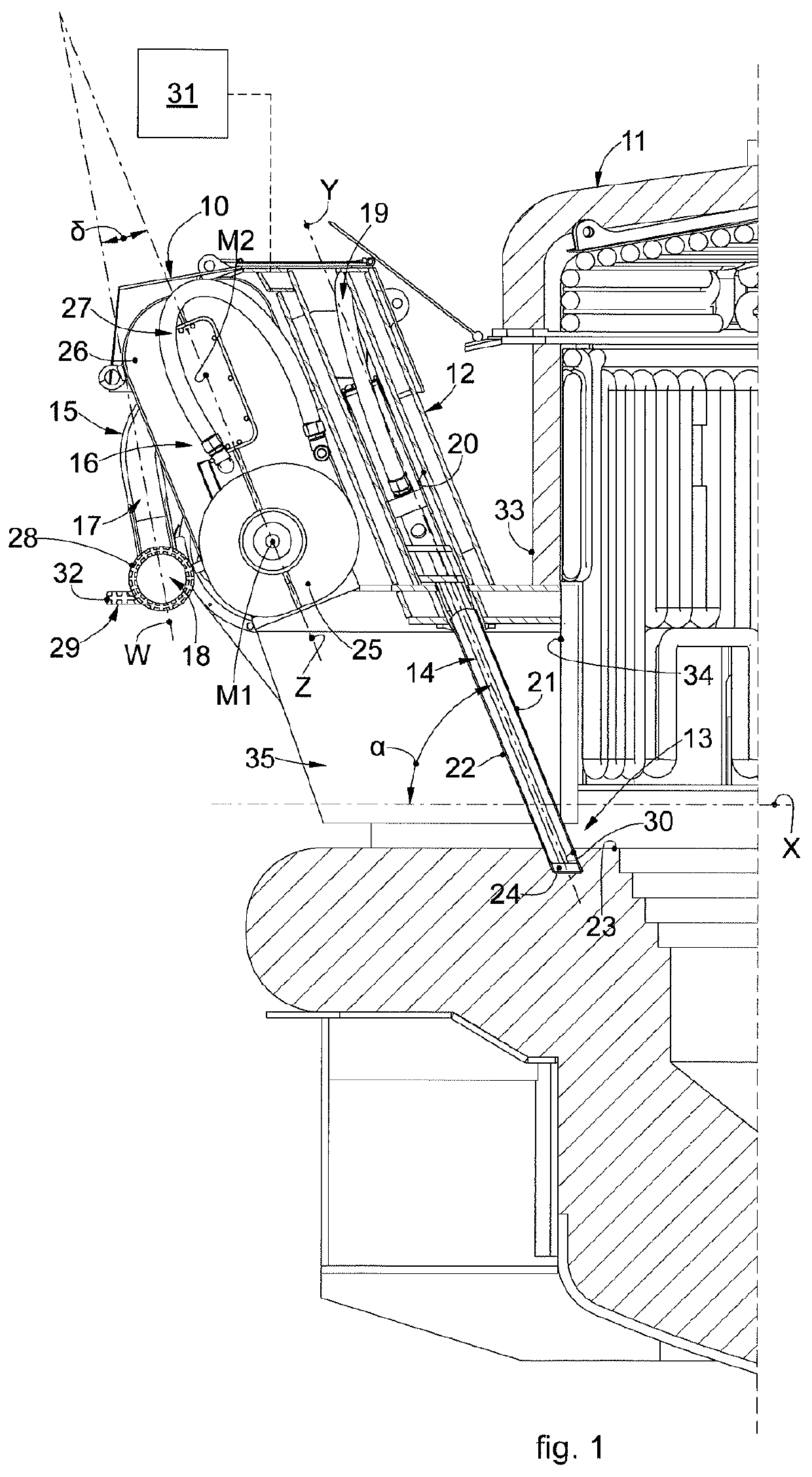
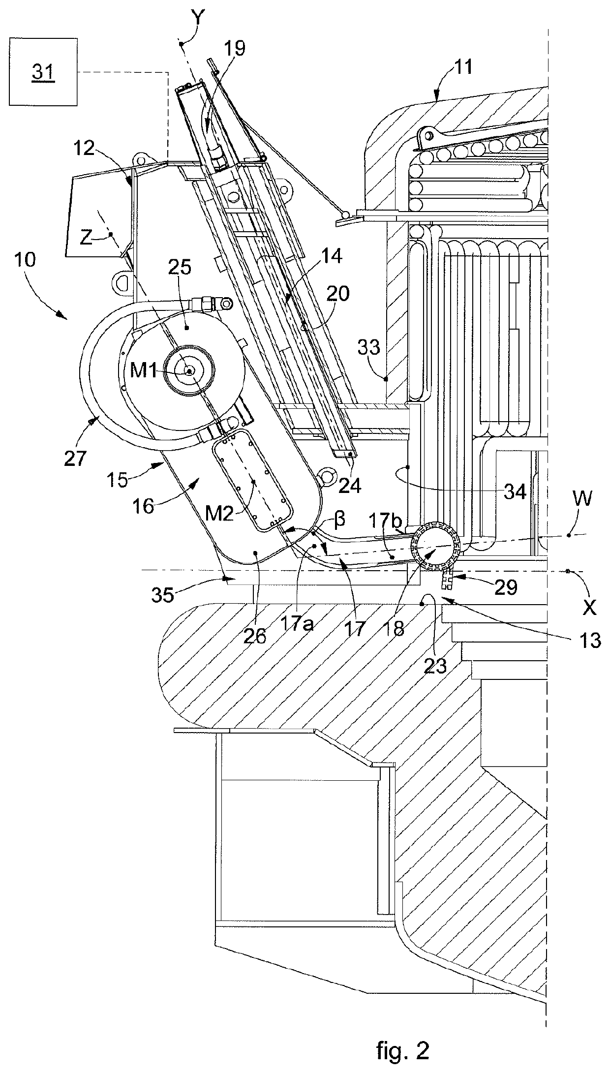
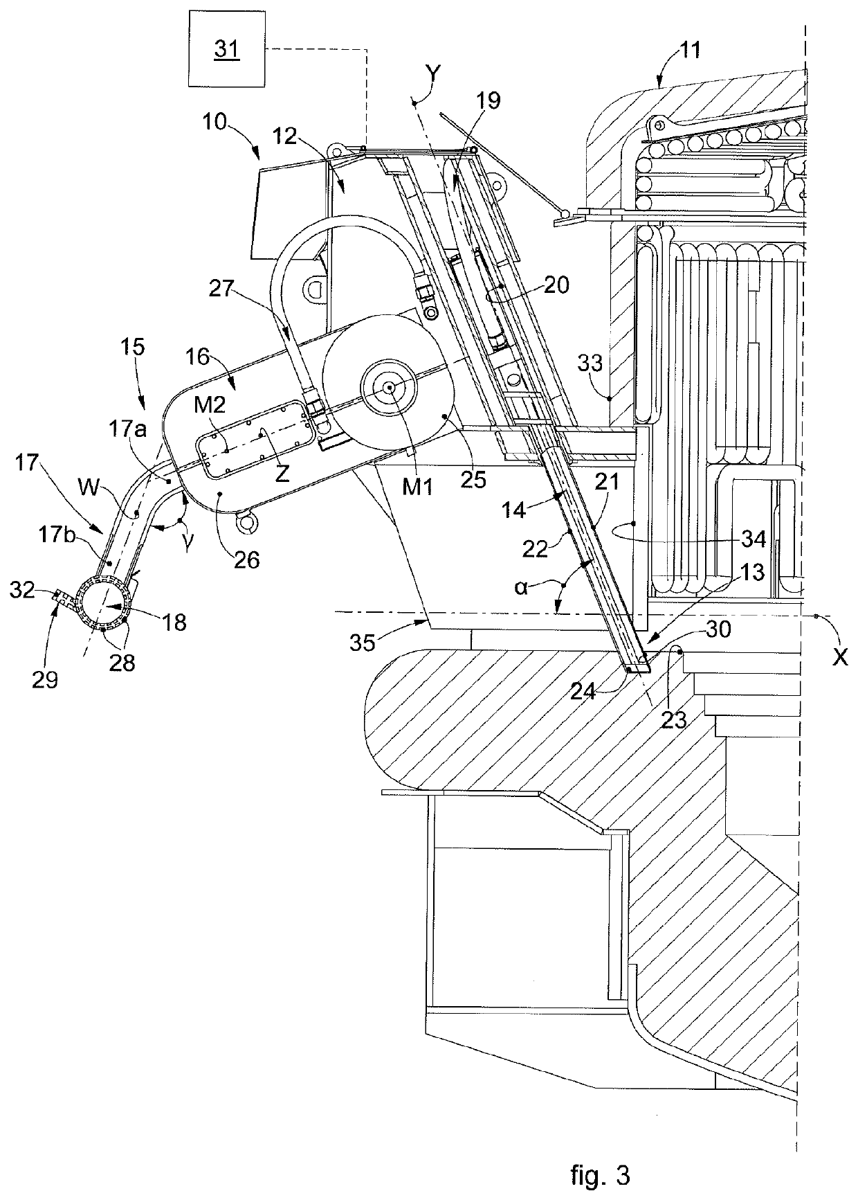
A slag door for a melting furnace for the production of steel is suitable to be associated with an aperture provided in a lateral wall of the melting furnace and to cooperate with a slag channel provided inside the melting furnace itself.

Description

FIELD OF THE INVENTION[0001]Embodiments described here concern a slag door for a melting furnace.[0002]In particular, the slag door according to the present invention is used in association with a metal melting furnace to allow the selective discharge of at least part of the slag layer produced during the melting processes for producing steel.BACKGROUND OF THE INVENTION[0003]A common metal melting furnace, for example of the electric arc type, essentially comprises a shell for containing the molten steel, a covering vault equipped with an openable cap, electrodes that drop through the vault and a suction plant for the fumes.[0004]An arc furnace normally comprises a slag door, typically positioned on the vertical wall of the shell, and communicating with the inside of the furnace through a tunnel, or slag channel, lined with refractory material (and / or with cooling elements). The slag door is mainly used to extract the slag, as well as for other activities such as loading additives a...

Claims


Application Information

Patent Timeline
IPC IPC(8): F27D3/15F27D25/00
CPCF27D25/001F27D3/1545F27D3/1536F27D1/1858F27D3/1563F27M2001/02F27M2003/13F27D3/159F27D3/1572F27D25/005F27D1/1866F27B3/19Y02P10/20F27B3/10F27D1/18F27D3/15
Inventor DA COSTA, PAULOSCOTTI, FRANCOBURIN, PAOLO
Owner DANIELI & C OFF MEC SPA
Why Eureka
Try Eureka