Apparatus for and a Method of Removing Contaminant Particles from a Component of an Apparatus

Active Publication Date: 2019-07-04
ASML NETHERLANDS BV
View PDF0 Cites 2 Cited by
  • Summary
  • Abstract
  • Description
  • Claims
  • Application Information

AI Technical Summary

Benefits of technology

The patent aims to prevent electrical breakdown between a component and a collection region by determining the magnitude of the applied voltage. Additionally, the invention provides a cost-effective way to remove contaminant particles from a device without having to open the metrology apparatus and require the presence of a technician.

Problems solved by technology

There are several potential sources of contaminant particles within a metrology tool, such as cleaning wipes used during servicing and maintenance of the tool.
The semiconductor wafer containing the structure being measured may itself introduce contaminant particles into the metrology tool as a result of contamination in the wafer handling system or front opening unified pods (FOUPs) used to store and transport the wafers.
The inventors have recognized that such contaminant particles can, under certain circumstances, result in the metrology tool causing damage to the wafer under measurement, which is undesirable as it can result in lower yield.
Contaminant particles may also impact the performance of the metrology tool in terms of accuracy, for example.

Method used


Image

  • Apparatus for and a Method of Removing Contaminant Particles from a Component of an Apparatus
  • Apparatus for and a Method of Removing Contaminant Particles from a Component of an Apparatus
  • Apparatus for and a Method of Removing Contaminant Particles from a Component of an Apparatus

Examples


Embodiment Construction

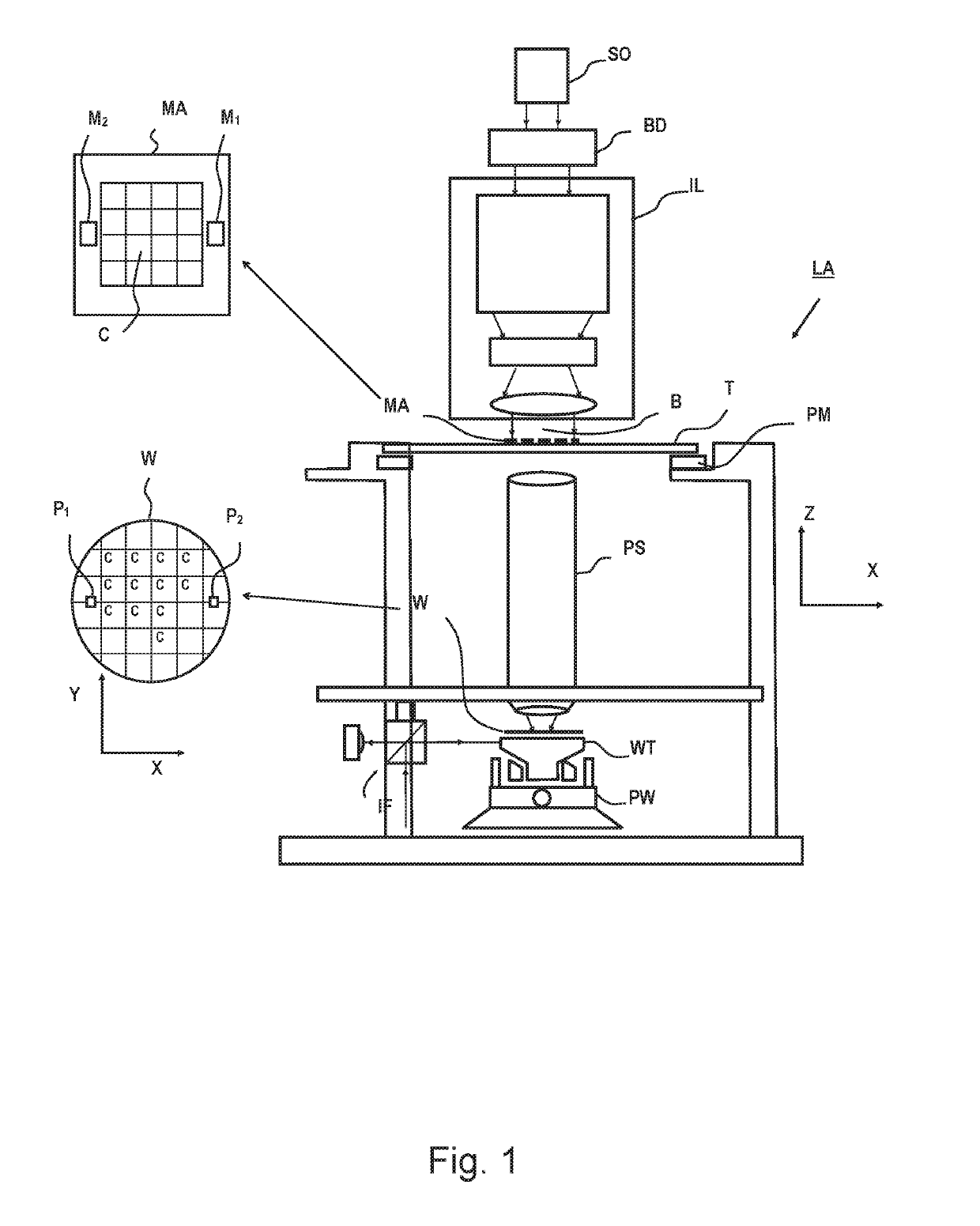
[0077]Before describing the invention in detail, it is instructive to present an example environment in the present invention may be implemented.

[0078]In the present document, the terms “radiation” and “beam” are used to encompass all types of electromagnetic radiation, including ultraviolet radiation (e.g. with a wavelength of 365, 248, 193, 157 or 126 nm) and EUV (extreme ultra-violet radiation, e.g. having a wavelength in the range of about 5-100 nm).

[0079]The term “reticle”, “mask” or “patterning device” as employed in this text may be broadly interpreted as referring to a generic patterning device that can be used to endow an incoming radiation beam with a patterned cross-section, corresponding to a pattern that is to be created in a target portion of the substrate. The term “light valve” can also be used in this context. Besides the classic mask (transmissive or reflective, binary, phase-shifting, hybrid, etc.), examples of other such patterning devices include a programmable ...


PUM


Abstract

An apparatus (300) for removing contaminant particles (205) from a component (202, 204) of an apparatus (140, MT), the contaminant particles giving rise to an ambient electric field (E), the apparatus comprising: a collection region (301) for attracting the particles, wherein the ambient electric field is at least between the component and the collection region; and an electric field generator configured to establish an applied electric field between the collection region and the component to cause the particles to be transported from the component to the collection region, wherein the electric field generator is configured to determine the polarity of the applied electric field based on the ambient electric field.

Description

FIELD[0001]The present disclosure relates to methods and apparatuses for removing contaminant particles from a component of an apparatus, optionally, a metrology apparatus.BACKGROUND[0002]In lithographic processes, it is desirable to make frequent measurements of the structures created, e.g., for process control and verification. Tools to make such measurement are typically called metrology tools (MET). Different types of inetrology tools for making such measurements are known, including scanning electron microscopes or various forms of scatterometer metrology tools.[0003]Scatterometers are versatile instruments which allow measurements of the parameters of a lithographic process by having a sensor in the pupil or a conjugate plane with the pupil of the objective of the scatterometer, measurements usually referred to as pupil based measurements, or by having the sensor in the image plane or a plane conjugate with the image plane, in which case the measurements are usually referred t...

Claims


Application Information

Patent Timeline
IPC IPC(8): B08B6/00G03F7/20
CPCB08B6/00G03F7/7065G03F7/7085G03F7/70916G03F7/70925
Inventor MAAS, TIM PETER JOHAN GERARDVAN HOUT, BARTOLOMEUS MARTINUS JOHANNESVAN BUEL, HENRICUS WILHELMUS MARIAZOETHOUT, FLORIS
Owner ASML NETHERLANDS BV
Why Eureka
Try Eureka