Two-piece electrical terminal

a two-piece, electrical terminal technology, applied in the direction of coupling contact members, coupling device connections, connections effected by permanent deformation, etc., can solve the problems of pins and receptacles being subjected to multiple adverse conditions, providing degradation of pin and socket connections,

Active Publication Date: 2011-07-12
TYCO ELECTRONICS LOGISTICS AG (CH)
View PDF21 Cites 26 Cited by
  • Summary
  • Abstract
  • Description
  • Claims
  • Application Information

AI Technical Summary

Problems solved by technology

For example, in the automotive field, when electrical connectors are required in a plurality of harness connections, the pins and receptacles are subjected to multiple adverse conditions.
First, vibration from the engine or road conditions sometimes provides degradation to the pin and socket connection.

Method used


Image

  • Two-piece electrical terminal
  • Two-piece electrical terminal
  • Two-piece electrical terminal

Examples


Embodiment Construction

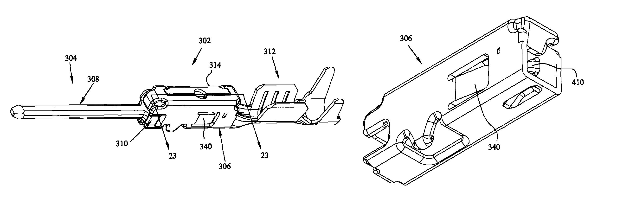
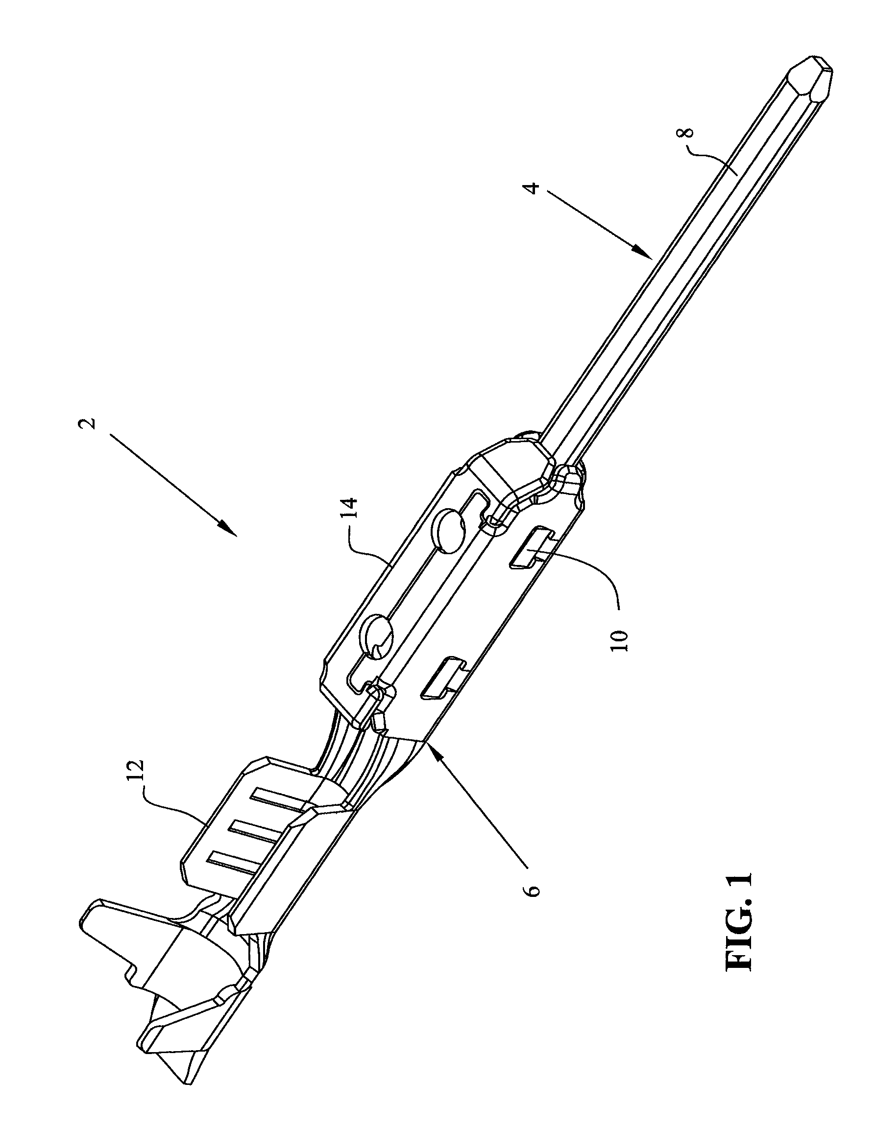
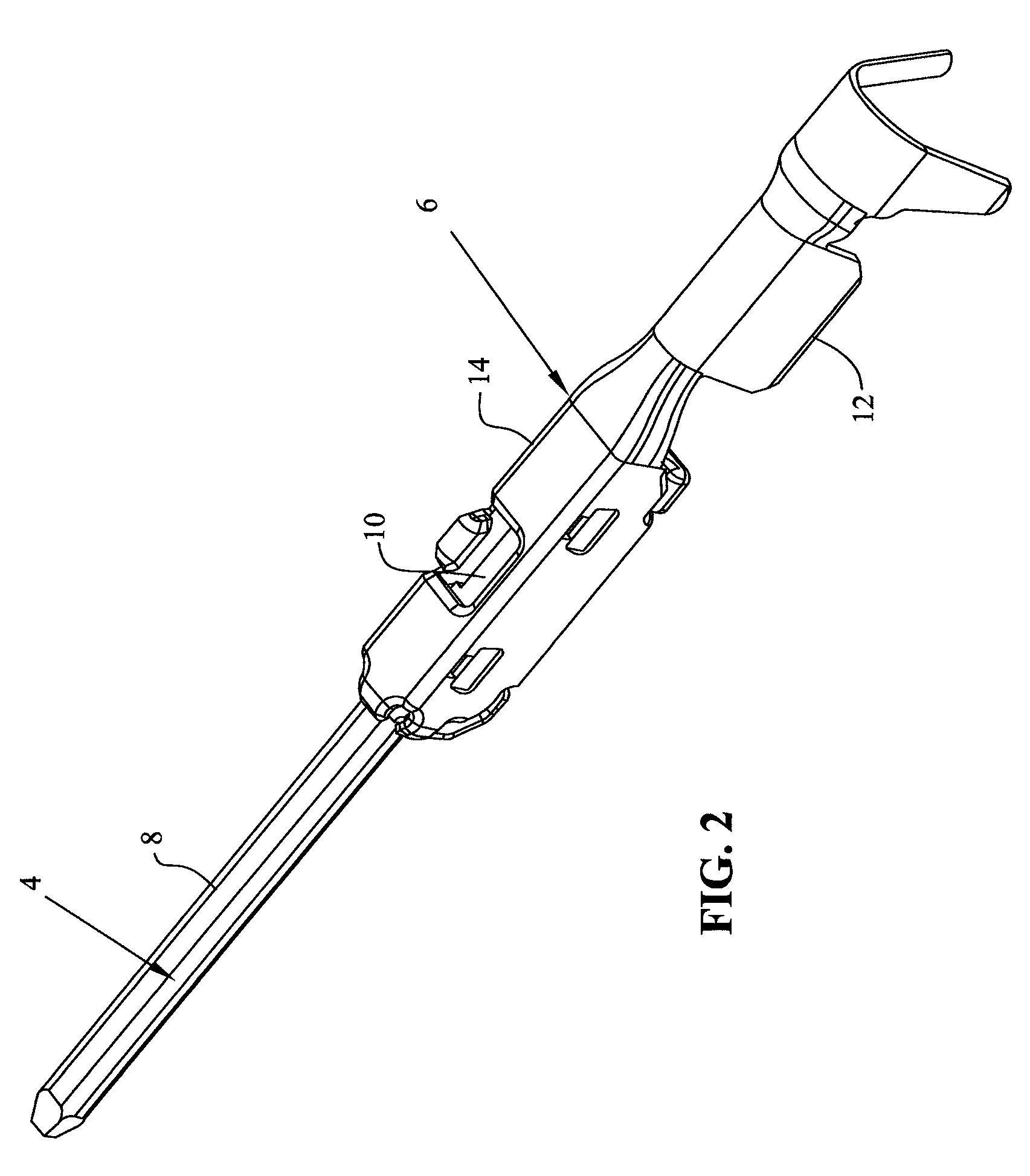
[0041]With reference first to FIGS. 1 and 2, a two piece electrical terminal is shown at 2 and includes a contact member 4 and a conductor connecting member 6. The contact member 4 is generally comprised of a contact section 8 and a retention section 10. The conductor connecting member 6 is comprised of a conductor connecting section 12 and a retaining member 14. With reference now to FIG. 3, the contact member 4 will be described in greater detail.

[0042]As shown in FIG. 3, the contact member 4 is shown separated from the conductor connecting member 6 to clearly show the contact section 8 as a pin terminal and the retention section 10 as integrally formed with the contact section 8. The retention section 10 is generally defined by a flat blade portion 16, having side edges 18 on one side thereof, and side edges 20 on the opposite side thereof. Undulations in the form of tabs 22 extend from the side edge 18, while undulations in the form of tabs 24 extend from side edge 20.

[0043]With...


PUM


Abstract

A two piece electrical terminal is shown where one part is comprised of a contact member having a contact section in the form of a pin and retention section. A conductor connecting member is comprised of a conductor connecting section and a retaining member. The contact member has a lug extending along one side thereof and the retaining member has a complementary opening which retains the contact member and conductor connecting member together.

Description

[0001]This application is a Continuation-in-Part, and claims the benefit of, U.S. patent application Ser. No. 11 / 540,219 filed Sep. 29, 2006, the complete disclosure of which is hereby expressly incorporated by reference.BACKGROUND OF THE INVENTION[0002]The subject invention relates to a pin terminal for electrical connection with a corresponding socket terminal.[0003]It is common in electrical connector technology to provide a plurality of wires for example in a harness configuration, attached to a connector housing, and another plurality of wires attached to another harness in yet another complementary connector. One of the connectors would have pin terminals while the other of the connectors would include a receptacle or socket terminal. Multiple considerations need to be considered in designing and manufacturing such terminals, particularly when the application to which the connectors will be subjected to, is considered.[0004]For example, in the automotive field, when electrical...

Claims


Application Information

Patent Timeline
Patent Type & Authority Patents(United States)
IPC IPC(8): H01R9/24
CPCH01R13/04
Inventor MYER, JOHN MARKMOLL, HURLEY CHESTERGRAHAM, LEO J.KINSEY, JR., FORREST I.
Owner TYCO ELECTRONICS LOGISTICS AG (CH)
Why Eureka
Try Eureka