Installation tool for use with a liner sleeve attachment

a technology for installing tools and liner sleeves, which is applied in the direction of manufacturing tools, threaded fasteners, mechanical devices, etc., can solve the problems of obstructing and interfering with the complete and rapid pull-out separation of fixtures, step may require a significant manual effort, and surface damage to the installed liner sleeves

Active Publication Date: 2011-08-30
PHYSICAL SYST
View PDF13 Cites 10 Cited by
  • Summary
  • Abstract
  • Description
  • Claims
  • Application Information

AI Technical Summary

Benefits of technology

[0010]In one alternative preferred form of the invention, the tapered nose piece can be substituted by a non-tapered nose piece adapted to engage a leading end of a cold working liner sleeve within the substrate opening. The installation tool is adapted to engage and pull upon the fixture pin, which has a sufficiently enlarged rear-end head for initially seating a rear-end or blind side sleeve flange against a blind side of the substrate and is then pulled forwardly through the liner sleeve for expanding the liner sleeve within the substrate opening for secure fastened relation with the substrate. As the fixture pin head expands the liner sleeve, the non-tapered nose piece and inner housing of the installation tool shift rearwardly to the retracted position, and a leading end of the outer housing advances into landed engagement with the substrate to provide a stable support structure against which the pulling force may react to withdraw the fixture pin from the installed attachment.

Problems solved by technology

One disadvantage associated with blind side-mounted attachments and the related installation tool as described above is that the tapered nose piece on the installation tool can obstruct and interfere with complete and rapid pull-out separation of the fixture pin from the liner sleeve, following flared deformation of the liner sleeve leading end.
Such step may require a significant exertion of manual effort, and, in some instances, may require the installation tool to be jockeyed or pivoted from side-to-side in order to extract the fixture pin head from the liner sleeve.
Such side-to-side movements may undesirably cause surface damage to the installed liner sleeve.
A similar problem arises in connection with so-called cold working sleeve attachments of the type having a flanged rear or blind side end in combination with a tubular cold working liner sleeve projecting from the flanged rear end into a substrate opening.
However, as the enlarged head of the fixture pin is pulled through the attachment sleeve, a nose of the installation tool can interfere with complete and rapid pull-out separation of the head from the liner sleeve.

Method used


Image

  • Installation tool for use with a liner sleeve attachment
  • Installation tool for use with a liner sleeve attachment
  • Installation tool for use with a liner sleeve attachment

Examples


Embodiment Construction

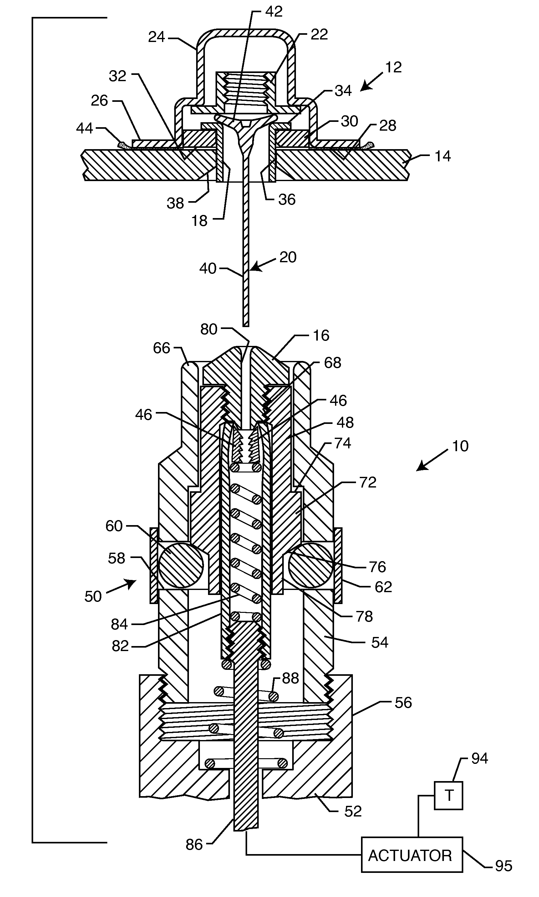
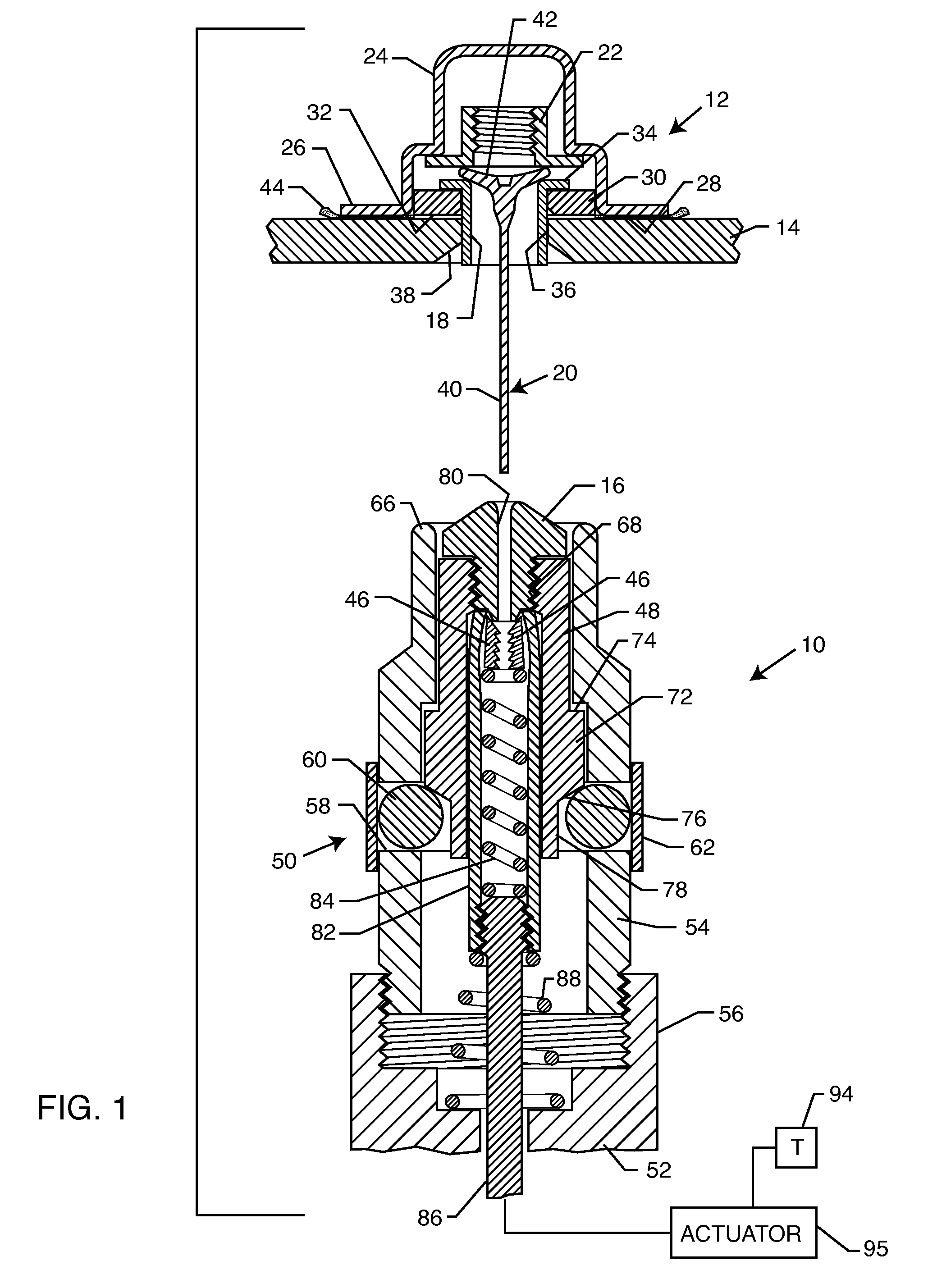
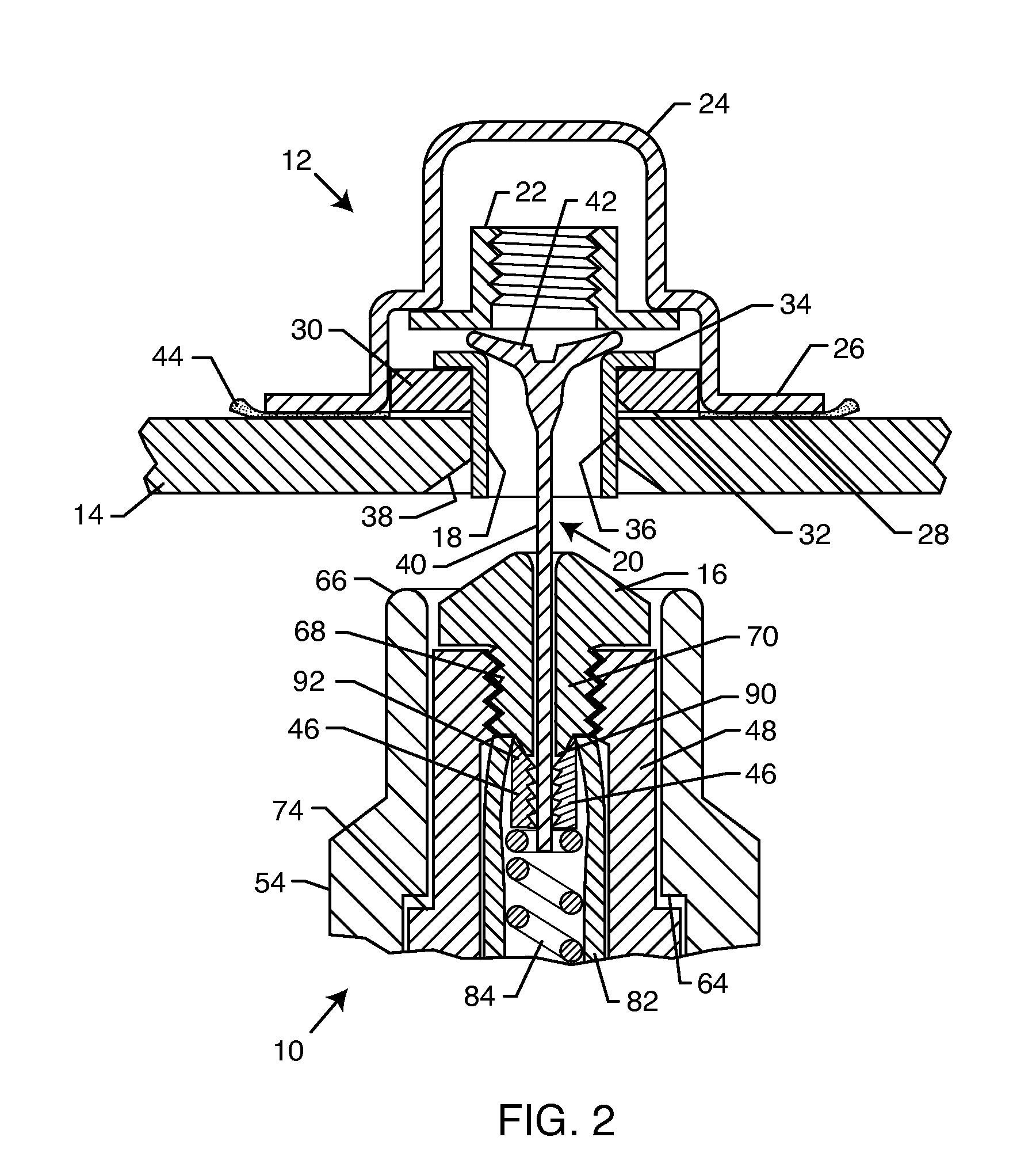
[0025]As shown in the exemplary drawings, an improved installation tool referred to generally in FIG. 1 by the reference numeral 10 is provided for use in installing a flared liner sleeve attachment 12 onto a substrate 14. The installation tool 10 includes a tapered nose piece 16 for engaging and flaring a leading end of a liner sleeve 18 forming a portion of the attachment 12, and for thereafter retracting the nose piece 16 from the liner sleeve 18 to permit complete and substantially unobstructed pull-out separation of a fixture pin 20 from the attachment.

[0026]The installation tool 10 of the present invention in particularly designed and adapted for use with a liner sleeve attachment 12 of the general type shown and described in U.S. Pat. No. 5,704,747, which is incorporated by reference herein. In this regard, the illustrative liner sleeve attachment 12 is particularly designed for use in a variety of aerospace, marine and automotive applications for supporting items such as ele...


PUM

PropertyMeasurementUnit
pulling forceaaaaaaaaaa
distanceaaaaaaaaaa
mechanical lockingaaaaaaaaaa

Abstract

An installation tool for use with a liner sleeve attachment, such as a nutplate assembly for mounting onto a substrate blind side as disclosed in U.S. Pat. No. 5,704,747. The installation tool includes retractable grip jaws for gripping and pulling a fixture pin protruding from the attachment, for initially advancing a tapered tool nose piece into deforming engagement with an attachment liner sleeve leading end to flare and / or expand the liner sleeve to lock the liner sleeve onto the substrate. Continued pulling action exerts a sufficient force to collapse a fixture pin head and thereby permit pull-removal of the fixture pin from the attachment. The nose piece is carried by a retractable inner housing normally retained in an advanced position for deforming the liner sleeve, and thereafter movable to a retracted position spaced from the liner sleeve to accommodate substantially unobstructed fixture pin separation from the attachment.

Description

BACKGROUND OF THE INVENTION[0001]This invention relates generally to an improved installation tool for use with a liner sleeve attachment or attachment assembly, such as an adhesive bonded nutplate attachment assembly of the type described in U.S. Pat. No. 5,704,747, which is incorporated by reference herein. More particularly, the installation tool of the present invention is designed for expanding and / or flared deformation of a leading end of a liner sleeve seated with an opening formed in a substrate, for mechanically clamping and locking the liner sleeve onto the substrate, and for thereafter pulling a fixture pin from the attachment for substantially complete removal therefrom without interference.[0002]U.S. Pat. No. 5,704,747 discloses an attachment or attachment assembly such as a nutplate assembly adapted for fixation onto the blind side of a selected substrate, such as onto a frame or panel used in an aerospace, marine or automotive application, wherein the attachment compr...

Claims


Application Information

Patent Timeline
Patent Type & Authority Patents(United States)
IPC IPC(8): B23P11/00F16B37/04B23P15/26B23P19/04
CPCB21J15/04B21J15/043B23P9/025F16B37/044F16B37/062Y10T29/49835Y10T29/53796Y10T29/53722Y10T29/53113Y10T29/53Y10T29/53752
Inventor HUTTER, III, CHARLES G.MADSON, BARRY L.
Owner PHYSICAL SYST
Why Eureka
Try Eureka