Transmission power control apparatus, propagation path estimating apparatus, transmission power control method, and propagation path estimating method

a technology of transmission power control and propagation path, which is applied in power management, power management, instruments, etc., can solve the problems of increasing the transmission power of pilot symbols, requiring high accuracy in transmission channel estimation, and less robust modulation schemes to frequency selective fading. achieve the effect of reducing unnecessary transmission power consumption

Inactive Publication Date: 2011-09-06
PANASONIC INTELLECTUAL PROPERTY CORP OF AMERICA
View PDF14 Cites 16 Cited by
  • Summary
  • Abstract
  • Description
  • Claims
  • Application Information

AI Technical Summary

Benefits of technology

[0012]According to the present invention, it is possible to reduce unnecessary transmission power consumed in transmission of pilot symbols.

Problems solved by technology

For example, a modulation scheme that is less robust to frequency selective fading requires high accuracy in transmission channel estimation, and, consequently, the transmission power of pilot symbols is increased.

Method used


Image

  • Transmission power control apparatus, propagation path estimating apparatus, transmission power control method, and propagation path estimating method
  • Transmission power control apparatus, propagation path estimating apparatus, transmission power control method, and propagation path estimating method
  • Transmission power control apparatus, propagation path estimating apparatus, transmission power control method, and propagation path estimating method

Examples


embodiment 1

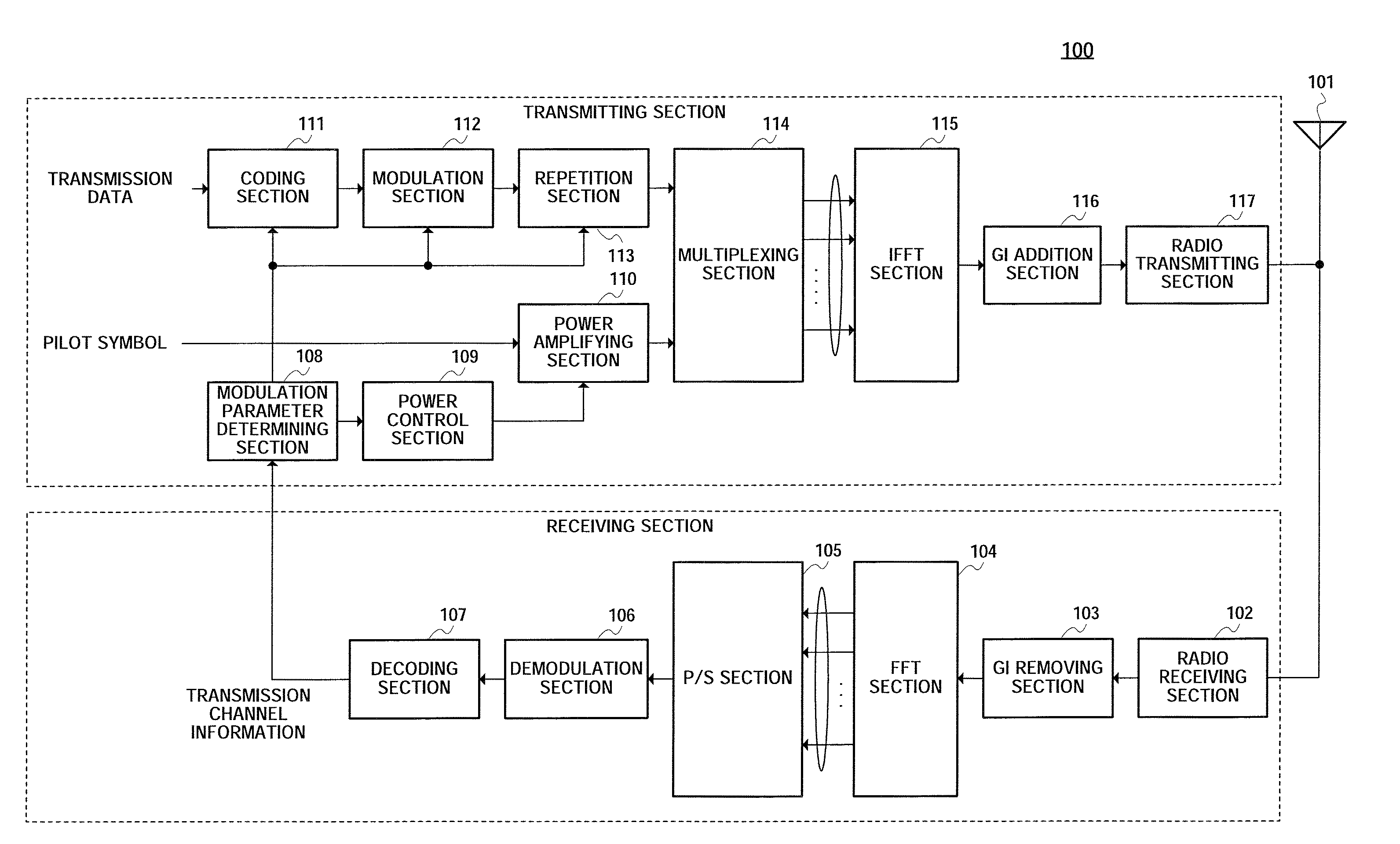
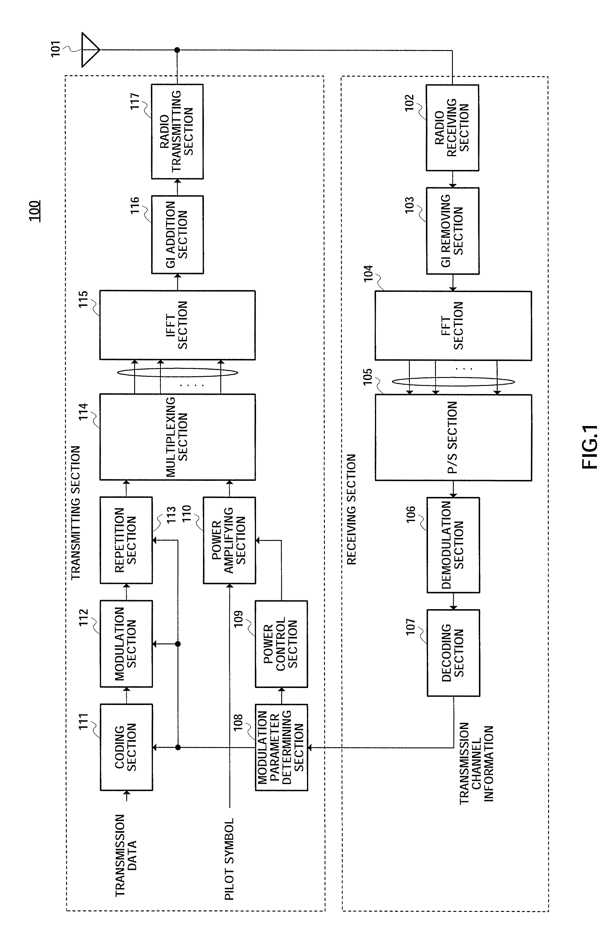
[0024]FIG. 1 is a block diagram showing a configuration of a base station apparatus provided with a radio transmitting apparatus according to Embodiment 1 of the present invention. Base station apparatus 100 of FIG. 1 has: antenna 101; radio receiving section 102; GI (Guard Interval) removing section 103; FFT (Fast Fourier Transform) section 104; (Parallel-to-Serial) conversion section 105; demodulation section 106; decoding section 107; modulation parameter determining section 108; power control section 109; power amplifying section 110; coding section 111; modulation section 112; repetition section 113; multiplexing section 114; IFFT (Inverse Fast Fourier Transform) section 115; GI addition section 116; and radio transmitting section 117. Also, radio receiving section 102, GI removing section 103, FFT section 104, P / S section 105, demodulation section 106 and decoding section 107 constitute a receiving section. Modulation parameter determining section 108, power control section 10...

embodiment 2

[0056]FIG. 9 is a block diagram showing a configuration of a communication terminal apparatus provided with a radio receiving apparatus according to this Embodiment 2. Communication terminal apparatus 200 of FIG. 9 has: antenna 201; radio receiving section 202; GI removing section 203; FFT section 204; demultiplexing section 205; modulation parameter determining section 206; power correction section 207; power attenuation section 208; transmission channel estimation section 209; transmission channel compensation section 210; demodulation section 211; and decoding section 212.

[0057]Radio receiving section 202 receives a radio signal transmitted from base station apparatus 100, described in Embodiment 1, via antenna 201. The radio signal is then subjected to predetermined radio processing (including down-conversion and A / D conversion). The received signal (radio frame) after radio processing is outputted to GI removing section 203. GI removing section 203 removes the GI added in a pre...


PUM


Abstract

A transmission power control apparatus capable of reducing unnecessary transmission power that is consumed in transmission of pilot symbols. In the apparatus, a power control part establishes, based on a repetition number of a data signal, a transmission power value of a pilot signal. For example, the power control part establishes, based on an improved reception quality when data signals as replicated in accordance with the repetition number of a data signal are combined, a transmission power value of a pilot signal at a level required and sufficient for meeting a target value of the reception quality of the other end of communication. A power amplifying part amplifies the pilot signal in accordance with the established transmission power value.

Description

TECHNICAL FIELD[0001]The present invention relates to a transmission power control apparatus and transmission power control method that perform transmission power control of pilot symbols used in transmission channel estimation in radio communication systems. The present invention also relates to a transmission channel estimation apparatus and transmission channel estimation method that perform transmission channel estimation using these pilot symbols.BACKGROUND ART[0002]In recent years, in radio communications, especially in mobile communications, in addition to voice, various information including image is transmitted. Along with this diversification of media of transmission, technologies for enabling high-speed transmission of information are in demand. The OFDM (Orthogonal Frequency Division Multiplexing) scheme is a multicarrier transmission scheme having features of high spectrum efficiency and low inter-symbol interference in the multipath environment, and is currently a focu...

Claims


Application Information

Patent Timeline
Patent Type & Authority Patents(United States)
IPC IPC(8): H04B7/00
CPCH04L1/0003H04L1/04H04L1/08H04W52/325H04L27/261H04L27/2626H04W52/42Y02B60/50
Inventor MATSUMOTO, ATSUSHIFUTAGI, SADAKINISHIO, AKIHIKO
Owner PANASONIC INTELLECTUAL PROPERTY CORP OF AMERICA
Why Eureka
Try Eureka