Fuel injection valve and method for forming orifice thereof

a technology of fuel injection valve and orifice, which is applied in the direction of machines/engines, soldering devices, applications, etc., can solve the problems of reducing the degree of freedom of design and the workability of orifices, reducing the degree of freedom of orifices, and reducing the work efficiency of the members used for the forming of orifices

Active Publication Date: 2011-09-13
HITACHI ASTEMO LTD
View PDF14 Cites 20 Cited by
  • Summary
  • Abstract
  • Description
  • Claims
  • Application Information

AI Technical Summary

Benefits of technology

[0011]The present invention makes it possible to increase the degree of freedom in design and the workability of orifices formed by press forming, in a fuel injection valve.

Problems solved by technology

As a result, press forming of orifices and recesses is restricted.
For example, the angle between a punch and a press forming face cannot be largely deviated from 90 degrees or a thickness of the punch has to be used if it is attempted to largely deviate the angle.
When deep recesses each of which has a large step are formed with a thickness of the punch, the work may weaken the strength of members used for the forming of the orifices.
Further, in the case where a large number of orifices are formed, when deep recesses of large diameters are intended to form, it is concerned that recesses of adjacent orifices and moreover a recess and an orifice may interfere with each other.
In particular, when it is attempted to change an inclination angle of each orifice with respect to a center axis line of a fuel injection valve for each orifice and orient the orifices in desired directions, interference between recesses or between a recess and an orifice tends to occur among specific orifices.
As a result, it is concerned that the degree of freedom in the design of orifices may reduce.

Method used


Image

  • Fuel injection valve and method for forming orifice thereof
  • Fuel injection valve and method for forming orifice thereof
  • Fuel injection valve and method for forming orifice thereof

Examples


Embodiment Construction

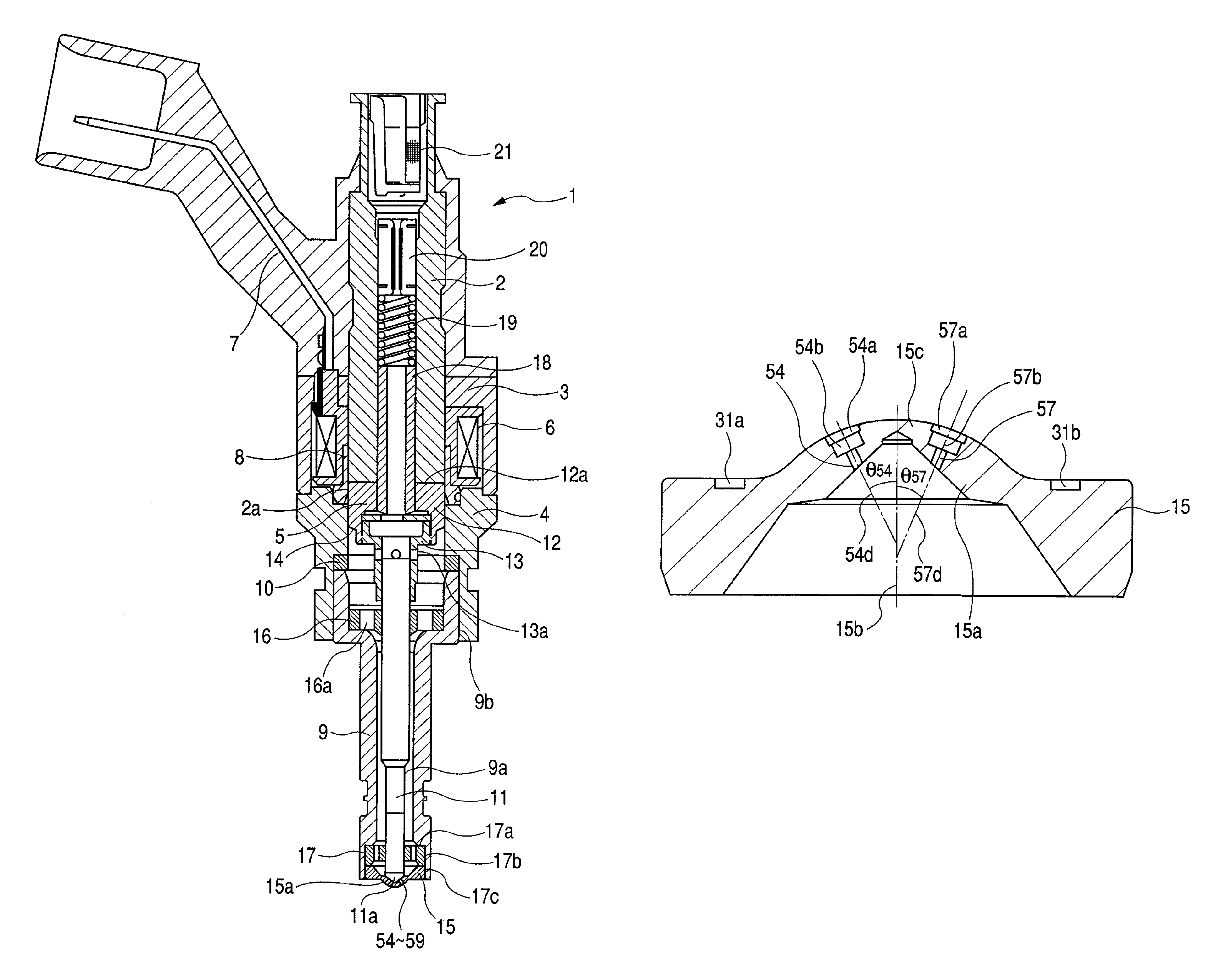
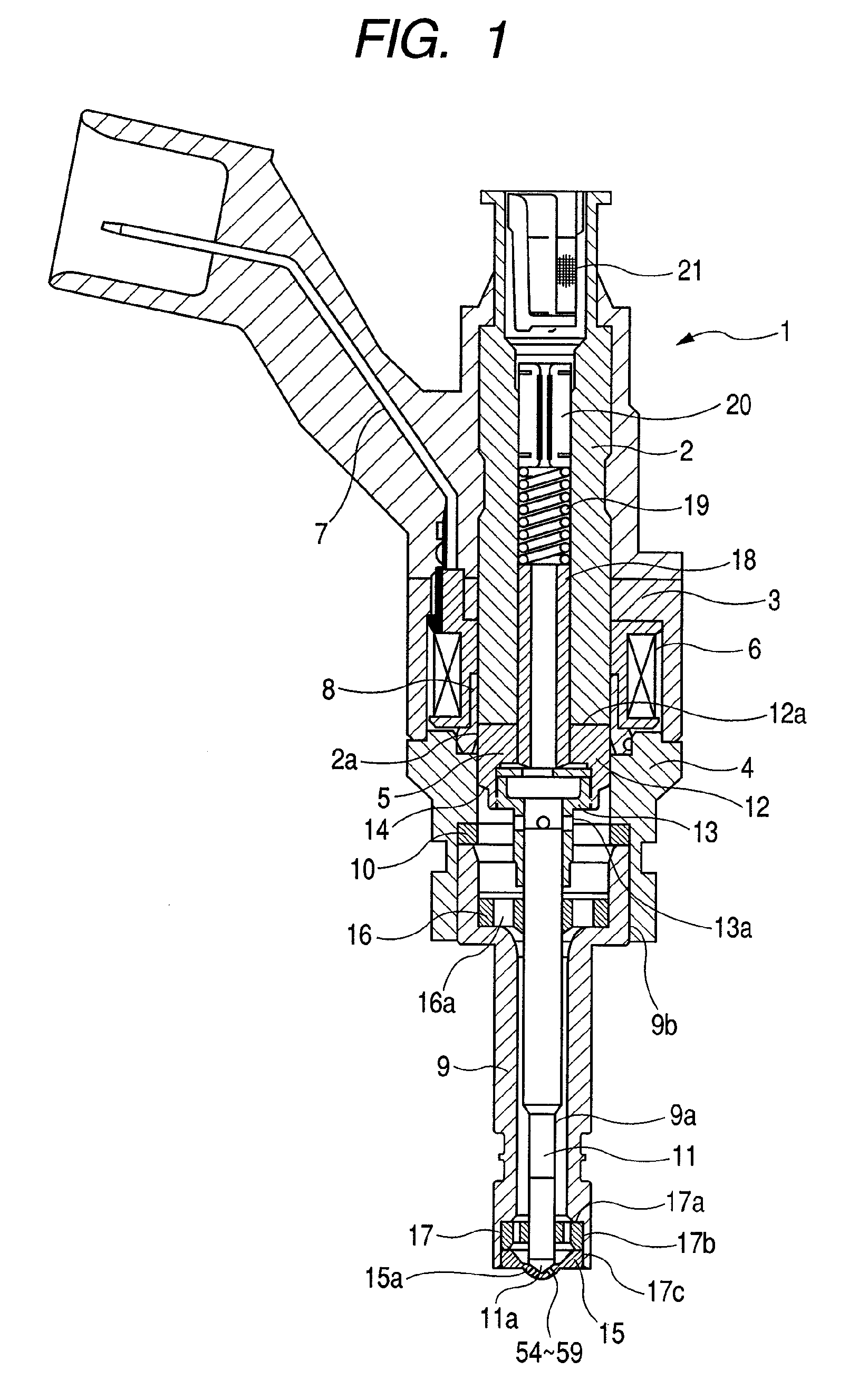
[0030]Embodiments according to the present invention are hereunder explained in detail in reference to drawings. FIG. 1 is a vertical sectional view showing a whole configuration of an injection valve according to an embodiment of the present invention. Here, the injection valve in the present embodiment is a fuel injection valve to inject a fuel such as gasoline and is used for injecting a fuel in the engine of an automobile.

[0031]A fuel injection valve assembly 1 comprises a magnetic circuit including a stationary core 2, a yoke 3, a housing 4 and a movable element 5, an electro magnetic coil 6 to energize the magnetic circuit, and a terminal bobbin 7 to supply electricity to the coil 6. A seal ring 8 is connected between the core 2 and the housing 4 and prevents a fluid such as a fuel from flowing into the coil 6.

[0032]Valve parts such as the movable element 5, a nozzle body 9, and a ring 10 to adjust a stroke of the movable element 5 are incorporated in the housing 4. The movabl...


PUM

PropertyMeasurementUnit
pressureaaaaaaaaaa
aspect ratioaaaaaaaaaa
heightaaaaaaaaaa

Abstract

A fuel injection valve comprises a convex portion prominently formed on an outer end surface of a nozzle body, stepped recesses each of which has plural steps formed by press forming on the convex portion, and multi orifices as fuel nozzle holes formed by press forming so that an outlet of each of the orifices is located at a bottom face of each of the stepped recesses. Furthermore, the fuel injection valve has plural sets each of which comprises one of the stepped recesses and the relevant orifice, the orifices incline to each other, and a step on a downstream side in each of the stepped recesses has a larger diameter than a step on an upstream side thereof.

Description

CLAIM OF PRIORITY[0001]The present application claims priority from Japanese patent application serial no. 2008-89155 filed on Mar. 31, 2008, the contents of which are hereby incorporated by reference into this application.FIELD OF THE INVENTION[0002]The present invention relates to a fuel injection valve used in an internal combustion engine of an automobile, and a method for forming orifices serving as a nozzle for the fuel injection valve.BACKGROUND OF THE INVENTION[0003]A fuel injection valve, wherein a convex portion is prominently formed in an orifice plate having orifices, plural recesses are formed at the convex portion, and an opening (outlet) of each of the orifices is formed at the bottom face of the relevant recess, has heretofore been known (for example refer to JP-A No. 77843 / 2007). In the fuel injection valve, the bottom face of a recess is formed perpendicularly to the axis line of the relevant orifice, consideration is made so that a fuel can be injected at the same...

Claims


Application Information

Patent Timeline
Patent Type & Authority Patents(United States)
IPC IPC(8): F02M61/00
CPCB21K1/20F02M61/1813F02M51/0671Y10T29/49405
Inventor HIGUMA, MASATOGUNJI, KENICHIKAWAHARA, KEIJISEKINE, ATSUSHI
Owner HITACHI ASTEMO LTD
Why Eureka
Try Eureka