
Inter-channel bias calibration for navigation satellite systems

a navigation satellite and calibration technology, applied in satellite radio beaconing, measurement devices, instruments, etc., can solve the problems of temperature and minute component differences, degrade position accuracy, and cancel all common errors between the base and the rover receiver, so as to reduce the inter-channel bias

Active Publication Date: 2011-09-20
JAVAD GNSS
View PDF6 Cites 25 Cited by
  • Summary
  • Abstract
  • Description
  • Claims
  • Application Information

AI Technical Summary

Benefits of technology

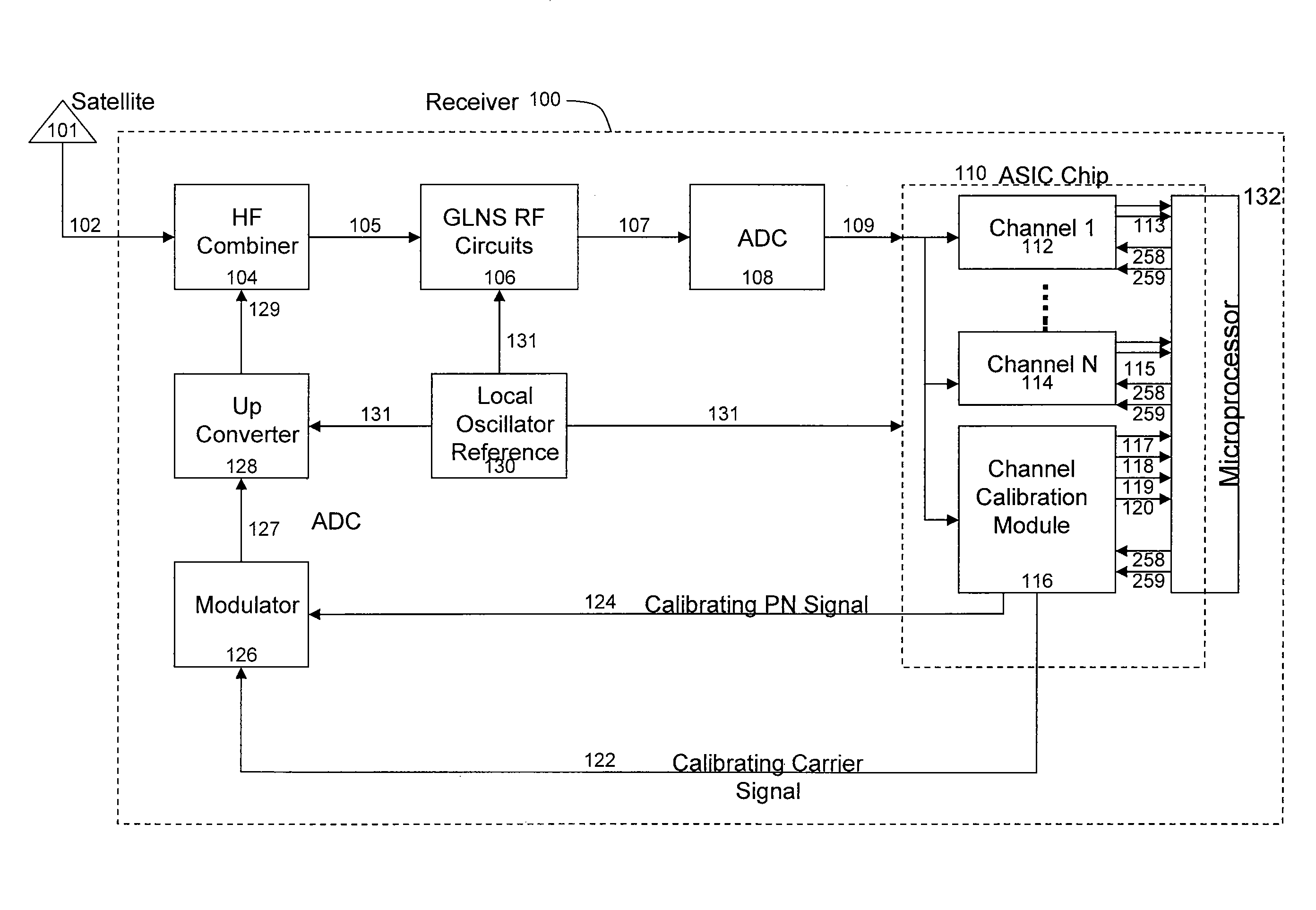
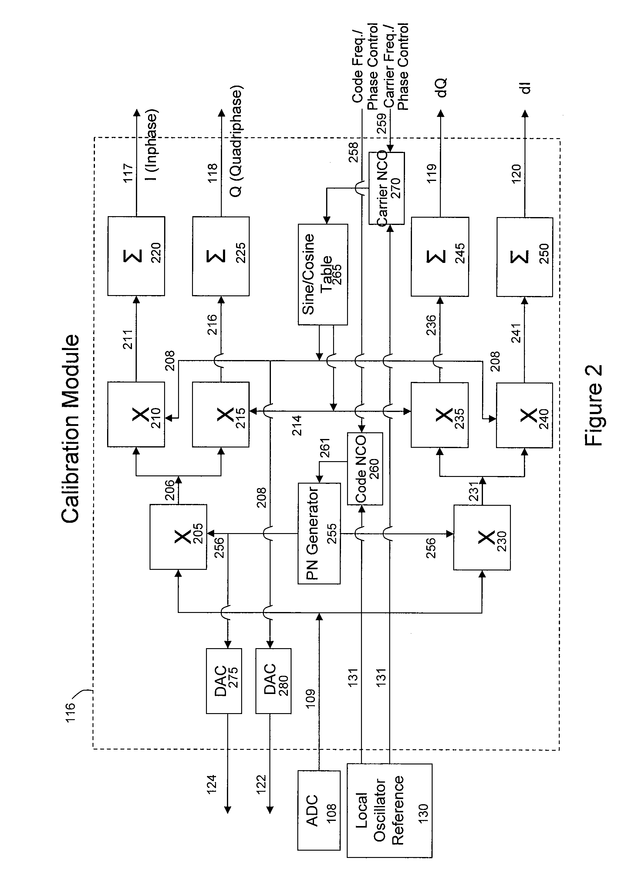
[0010]Embodiments of the present invention are directed to calibrating GLONASS inter-channel biases. An embodiment generates a reference signal and measures a bias delay associated with front-end circuitry of a navigation receiver by comparing a delayed reference signal with the reference signal. The delayed reference signal is based upon propagation of the reference signal through the front-end circuitry of the navigation receiver. The front end circuitry processes the reference signal and a received satellite signal. A calibration module generates a correction signal to reduce inter-channel bias. In another embodiment, a microprocessor may generate the correction signal.

Problems solved by technology

In technical terminology, GLONASS satellites cause inter-channel biases which, if not taken into account, can significantly degrade position accuracy.
Fortunately, all common errors between the Base and the Rover receivers are cancelled.
Even in the best case where the Base and the Rover receivers are from the same manufacturer and have identical design, components, and manufacturing dates, there is still the issue of temperature and minute component differences.
The magnitude of the GLONASS inter-channel biases can prohibit the use of GLONASS satellites for precision applications.
When the objective is to achieve centimeter and sub-centimeter accuracy, dealing with GLONASS inter-channel biases is not an easy task.
Dealing with the problem in this manner does not allow the user to know why their GPS+GLONASS receiver does not show any improvement over GPS-only receivers.
When the receiver firmware cannot isolate the GLONASS satellites with high inter-channel biases it provides inaccurate results.
This is a serious problem which causes the user to accept faulty results.
This is a positive step forward but by no means can cure the problem because there are still differences between electronic components compared to the sample, and their characteristics vary by temperature and time.

Method used


Image

  • Inter-channel bias calibration for navigation satellite systems
  • Inter-channel bias calibration for navigation satellite systems
  • Inter-channel bias calibration for navigation satellite systems

Examples


Embodiment Construction

[0018]The following description is presented to enable a person of ordinary skill in the art to make and use the invention, and is provided in the context of particular applications and their requirements. Various modifications to the embodiments will be readily apparent to those skilled in the art, and the generic principles defined herein may be applied to other embodiments and applications without departing from the spirit and scope of the invention. Moreover, in the following description, numerous details are set forth for the purpose of explanation. However, one of ordinary skill in the art will realize that the invention might be practiced without the use of these specific details. In other instances, well-known structures and devices are shown in block diagram form in order not to obscure the description of the invention with unnecessary detail. Thus, the present invention is not intended to be limited to the embodiments shown, but is to be accorded the widest scope consisten...


PUM


Abstract

Dynamic inter-channel bias calibration of a navigational receiver is provided. A reference signal is propagated through front end circuitry of the receiver. A delay caused by the propagation of the reference signal through the front end circuitry is measured. The inter-channel bias of the navigational receiver is reduced using the measured delay associated with the front end circuitry of the receiver.

Description

FIELD OF THE INVENTIONBackground[0001]1. Field[0002]The present invention relates to calibration of inter-channel bias in navigation satellite systems.[0003]2. Related Art[0004]Navigation receivers that utilize the signals of the global navigation satellite systems GPS and GLONASS enable various positioning tasks with very high accuracy. A GLONASS receiver receives and processes radio signals transmitted by the navigation satellites. The satellite signals are carrier harmonic signals that are modulated by pseudo-random binary codes which, on the receiver side, are used to measure the delay relative to a local reference clock. These delay measurements are used to determine the so-called pseudo-ranges between the receiver and the satellites. The pseudo-ranges are different from the true geometric ranges because the receiver's local clock is different from the satellite onboard clocks. If the number of satellites in sight is greater than or equal to four, then the measured pseudo-range...

Claims


Application Information

Patent Timeline
Patent Type & Authority Patents(United States)
IPC IPC(8): G01S19/23
CPCG01S19/235
Inventor YUDANOV, SERGEYVARYUKHIN, VYACHESLAVSHURYGIN, NIKOLAYSILA-NOVITSKIY, STANISLAVASHJAEE, JAVAD
Owner JAVAD GNSS
Learn More