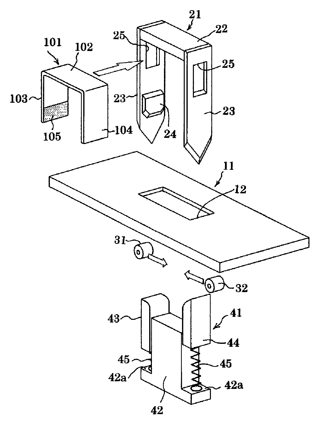
Tape type binding apparatus and paper staple
a technology of paper staples and tapes, which is applied in the field of tape type binding apparatus and paper staples, can solve the problems of mixing staples that need to be removed, difficult to release adhesive tapes without damaging papers, and extra time and labor, etc., and achieves the effect of simple binding process, easy unbounding, and stack of stapled papers
- Summary
- Abstract
- Description
- Claims
- Application Information
AI Technical Summary
Benefits of technology
Problems solved by technology
Method used
Image
Examples
embodiment 1
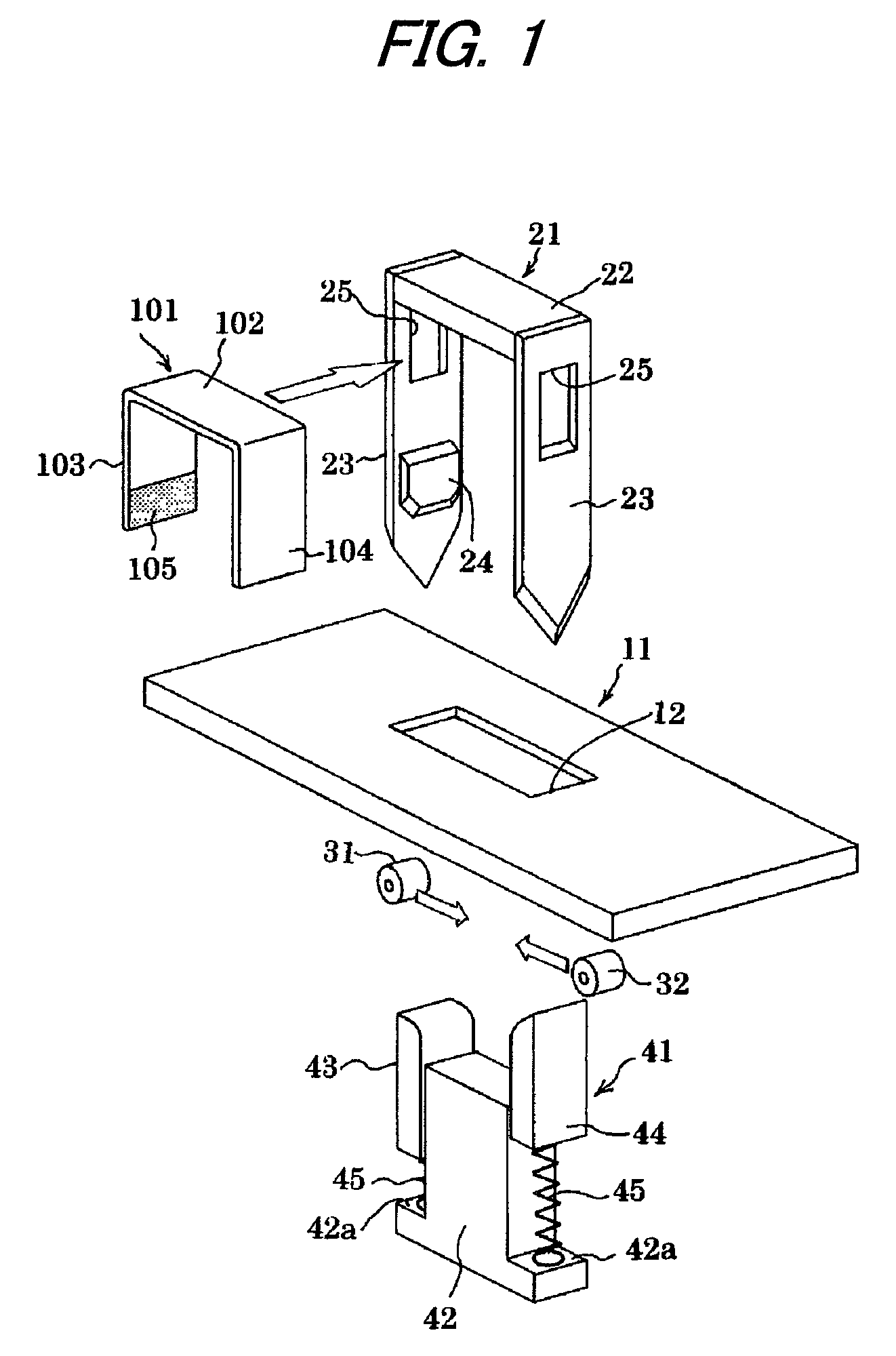
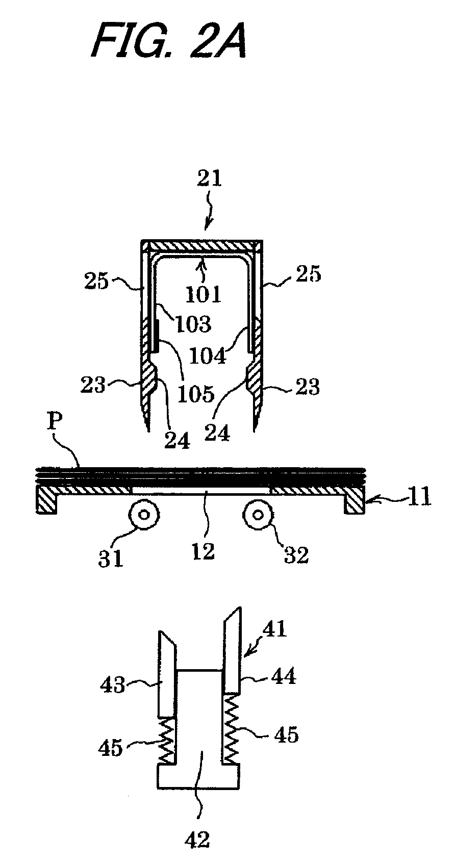
[0025]FIG. 1 shows a binding mechanism of a tape type binding apparatus. Reference numeral 101 designates a paper made binding member that is previously bent in a U-shape, and in the following description, the paper made binding member is referred to as a paper staple. The paper staple 101 includes a horizontal crown portion 102, a pair of leg portions 103, 104 which extend to a lower side from both left and right ends of the horizontal crown portion 102. Only one of the leg portions (the leg portion 103 on the left side in the drawing) is coated with an adhesive agent 105 at an inner face thereof, and the left and right leg portions 103, 104 are adhered by folding the right leg portion 104 to an inner side, and thereafter, folding the left leg portion 103 to the inner side.
[0026]Reference numeral 11 designates a paper table for receiving papers, and a cutter portion 21 is disposed above the paper table 11. The cutter portion 21 is a U-shape member in which cutter blades 23 are atta...
embodiment 2
[0042]FIG. 3A to FIG. 3F show a second embodiment in which cams 33, 34 are used instead of the rollers 31, 32 as the pair of pressing members for making the two leg portions 103, 104 of the paper staple 101 to become close to each other. Configurations and operations of other portions are the same as those of the first embodiment.
[0043]A distance between axes of the pair of left and right cams 33, 34 is set to be wider than a transverse width of the cutter portion 21. When the cutter portion 21 is moved down from an initial state shown in FIG. 3A, the pair of cams 33, 34 are retreated from the vertical moving paths of the cutter blades 23 by rotating in opening directions as shown in FIG. 3B.
[0044]Subsequently, when the cutter portion 21 reaches a moving down end as shown in FIG. 3C, the cams 33, 34 are rotated in directions of becoming close to each other, thereby moving into the inner side of the cutter portion 21 through the rectangular holes 25 of the cutter blades 23 and pushin...
embodiment 3
[0046]Although the two leg portions 103, 104 of the paper staple 101 are folded to almost 90 degrees by the pair of clinchers 43, 44 of the clincher portion 41 in the first embodiment and the second embodiment, the clinchers 43, 44 may be omitted by providing a folding function to rollers or cams which move the leg portions of the paper staple proximate to the inner side.
[0047]According to a third embodiment, a range of expanding and contracting an interval between a pair of left and right rollers is wider than that of the first embodiment. As shown in FIG. 4, upper ends of a pair of left and right rollers 35, 36 are arranged so as to be at a height that is substantially equal to the surface of the paper table 11.
[0048]FIG. 5A to FIG. 5E show steps of a binding operation. The pressing piece 42 is arranged below the paper table 11. In other words, the clincher portion 41 according to the first or second embodiments is arranged, but without the left and right clinchers 43, 44.
[0049]FI...
PUM
 Abstract
Description
Claims
Application Information
 - R&D
- Intellectual Property
- Life Sciences
- Materials
- Tech Scout
- Unparalleled Data Quality
- Higher Quality Content
- 60% Fewer Hallucinations
Browse by: Latest US Patents, China's latest patents, Technical Efficacy Thesaurus, Application Domain, Technology Topic, Popular Technical Reports.
© 2025 PatSnap. All rights reserved.Legal|Privacy policy|Modern Slavery Act Transparency Statement|Sitemap|About US| Contact US: help@patsnap.com


