Tape type binding apparatus and paper staple

Active Publication Date: 2009-05-28
MAX CO LTD
View PDF4 Cites 12 Cited by
  • Summary
  • Abstract
  • Description
  • Claims
  • Application Information

AI Technical Summary

Benefits of technology

[0012]One or more embodiments of the invention provides a tape type binding apparatus and a paper s

Problems solved by technology

However, when recycling the papers bound with staples made of metal lines, the mixed staples needs to be removed.
Nevertheless, extra time and labor is required for such a sep

Method used


Image

  • Tape type binding apparatus and paper staple
  • Tape type binding apparatus and paper staple
  • Tape type binding apparatus and paper staple

Examples


embodiment 1

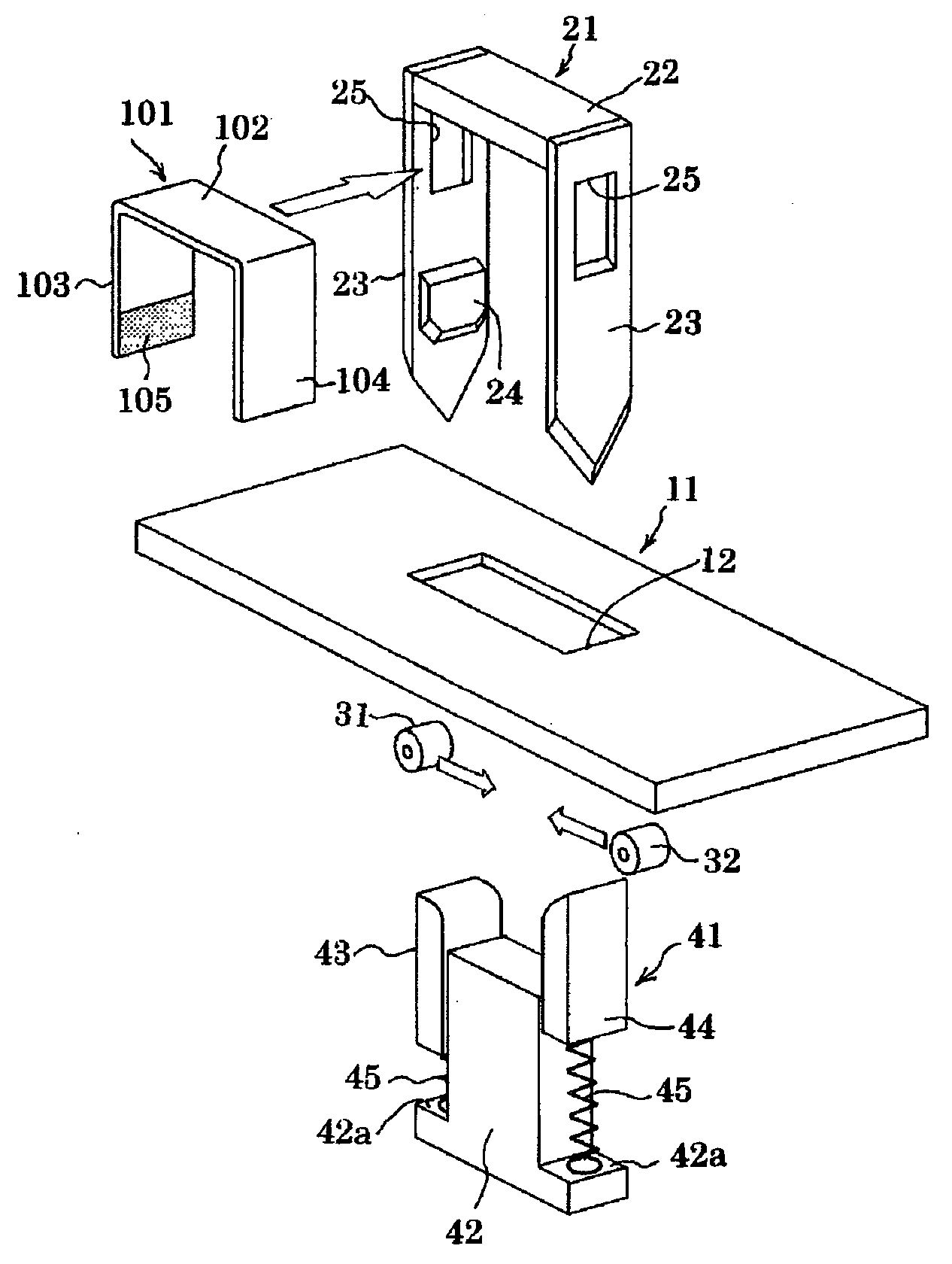
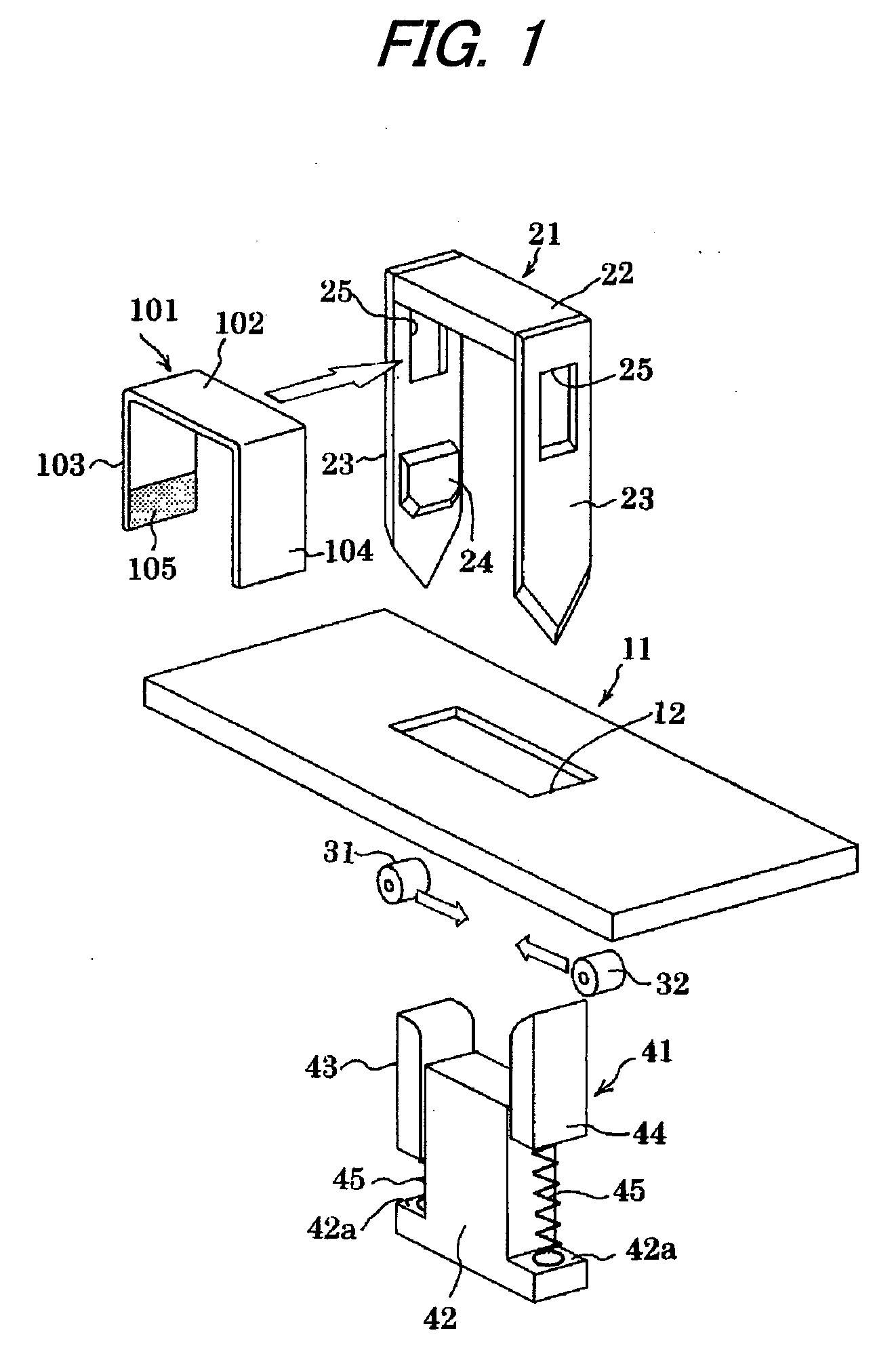
[0025]FIG. 1 shows a binding mechanism of a tape type binding apparatus. Reference numeral 101 designates a paper made binding member that is previously bent in a U-shape, and in the following description, the paper made binding member is referred to as a paper staple. The paper staple 101 includes a horizontal crown portion 102, a pair of leg portions 103, 104 which extend to a lower side from both left and right ends of the horizontal crown portion 102. Only one of the leg portions (the leg portion 103 on the left side in the drawing) is coated with an adhesive agent 105 at an inner face thereof, and the left and right leg portions 103, 104 are adhered by folding the right leg portion 104 to an inner side, and thereafter, folding the left leg portion 103 to the inner side.

[0026]Reference numeral 11 designates a paper table for receiving papers, and a cutter portion 21 is disposed above the paper table 11. The cutter portion 21 is a U-shape member in which cutter blades 23 are atta...

embodiment 2

[0042]FIG. 3A to FIG. 3F show a second embodiment in which cams 33, 34 are used instead of the rollers 31, 32 as the pair of pressing members for making the two leg portions 103, 104 of the paper staple 101 to become close to each other. Configurations and operations of other portions are the same as those of the first embodiment.

[0043]A distance between axes of the pair of left and right cams 33, 34 is set to be wider than a transverse width of the cutter portion 21. When the cutter portion 21 is moved down from an initial state shown in FIG. 3A, the pair of cams 33, 34 are retreated from the vertical moving paths of the cutter blades 23 by rotating in opening directions as shown in FIG. 3B.

[0044]Subsequently, when the cutter portion 21 reaches a moving down end as shown in FIG. 3C, the cams 33, 34 are rotated in directions of becoming close to each other, thereby moving into the inner side of the cutter portion 21 through the rectangular holes 25 of the cutter blades 23 and pushin...

embodiment 3

[0046]Although the two leg portions 103, 104 of the paper staple 101 are folded to almost 90 degrees by the pair of clinchers 43, 44 of the clincher portion 41 in the first embodiment and the second embodiment, the clinchers 43, 44 may be omitted by providing a folding function to rollers or cams which move the leg portions of the paper staple proximate to the inner side.

[0047]According to a third embodiment, a range of expanding and contracting an interval between a pair of left and right rollers is wider than that of the first embodiment. As shown in FIG. 4, upper ends of a pair of left and right rollers 35, 36 are arranged so as to be at a height that is substantially equal to the surface of the paper table 11.

[0048]FIG. 5A to FIG. 5E show steps of a binding operation. The pressing piece 42 is arranged below the paper table 11. In other words, the clincher portion 41 according to the first or second embodiments is arranged, but without the left and right clinchers 43, 44.

[0049]FI...


PUM


Abstract

A tape type binding apparatus includes a cutter portion formed in a U-shape inside which a paper staple is held, a paper table formed with a drawing hole through which cutter blades of the cutter portion can be inserted, a pair of pressing members arranged on respective sides of the drawing hole, and a pressing piece arranged below the center of the drawing hole. The cutter blades and leg portions of the paper staple penetrate a stack of sheets placed on the paper table by moving down the cutter portion, the pair of pressing members folds the leg portions of the paper staple to inner sides by moving toward the center of the drawing hole through rectangular holes formed on respective cutter blades, and the pressing piece presses and bonds the folded leg portions by relatively moving up with respect to the paper table.

Description

TECHNICAL FIELD[0001]The present invention relates to a tape type binding apparatus and a paper staple, in which the tape type binding apparatus binds a stack of papers such as documents with a paper made adhesive tape.BACKGROUND ART[0002]Conventionally, a stapler is used when simply binding a stack of papers. However, when recycling the papers bound with staples made of metal lines, the mixed staples needs to be removed. Also when disposing such a stack of stapled papers, it is preferable to separate the staples from the papers in view of environmental protection. Nevertheless, extra time and labor is required for such a separating work.[0003]As a proposal for dispensing with such time and labor, there a binding apparatus which binds a stack of papers by a paper made adhesive tape in stead of a metal staple (see, e.g., JP-A-8-039959 and JP-A-10-000871). The binding apparatus uses a paper made adhesive tape roll, and includes a slider having a clamp plate for clamping papers and a l...

Claims


Application Information

Patent Timeline
IPC IPC(8): B42B5/04B42B5/08
CPCB42B4/00B42P2241/26B42C9/0056B42B5/08B25C5/04B42B5/00
Inventor AOKI, AKIRAUDAGAWA, HIROSHITAKEUCHI, SHINICHI
Owner MAX CO LTD
Why Eureka
Try Eureka